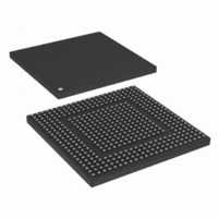
MPC8308CVMAFD Freescale Semiconductor, MPC8308CVMAFD Datasheet - Page 36

MPC8308CVMAFD
Manufacturer Part Number
MPC8308CVMAFD
Description
MPU POWERQUICC II PRO 473MAPBGA
Manufacturer
Freescale Semiconductor
Series
PowerQUICC II PROr
Datasheets
1.MPC8308VMAGD.pdf
(90 pages)
2.MPC8308VMAGD.pdf
(2 pages)
3.MPC8308VMAGD.pdf
(1170 pages)
4.MPC8308VMAGD.pdf
(14 pages)
Specifications of MPC8308CVMAFD
Processor Type
MPC83xx PowerQUICC II Pro 32-Bit
Speed
333MHz
Voltage
1V
Mounting Type
Surface Mount
Package / Case
473-MAPBGA
Product
Network Processor
Data Rate
256 bps
Frequency
333 MHz
Supply Voltage (max)
3.6 V
Supply Voltage (min)
3 V
Supply Current (max)
5 uA
Maximum Operating Temperature
+ 105 C
Minimum Operating Temperature
- 40 C
Interface
I2C, JTAG, SPI
Mounting Style
SMD/SMT
Core Size
32 Bit
Cpu Speed
333MHz
Digital Ic Case Style
MAPBGA
No. Of Pins
473
Operating Temperature Range
-40°C To +105°C
Peak Reflow Compatible (260 C)
Yes
Rohs Compliant
Yes
Leaded Process Compatible
Yes
Lead Free Status / RoHS Status
Lead free / RoHS Compliant
Features
-
Lead Free Status / Rohs Status
Lead free / RoHS Compliant
Available stocks
Company
Part Number
Manufacturer
Quantity
Price
Company:
Part Number:
MPC8308CVMAFD
Manufacturer:
Freescale Semiconductor
Quantity:
10 000
Company:
Part Number:
MPC8308CVMAFDA
Manufacturer:
Freescale Semiconductor
Quantity:
10 000
PCI Express
11.3
The ports on the two ends of a link must transmit data at a rate that is within 600 parts per million (ppm)
of each other at all times. This is specified to allow bit rate clock sources with a ±300 ppm tolerance.
11.4
Following is a summary of the specifications for the physical layer of PCI Express on this device. For
further details as well as the specifications of the transport and data link layer please use the PCI Express
Base Specification, Rev. 1.0a.
11.4.1
Table 34
specified at the component pins.
36
Unit interval
Differential peak-to-peak
output voltage
De-Emphasized
differential output voltage
(ratio)
Minimum TX eye width
Maximum time between
the jitter median and
maximum deviation from
the median
Parameter
defines the specifications for the differential output at all transmitters (TXs). The parameters are
Clocking Dependencies
Physical Layer Specifications
Differential Transmitter (TX) Output
MPC8308 PowerQUICC II Pro Processor Hardware Specification, Rev. 2
Table 34. Differential Transmitter (TX) Output Specifications
T
TX-EYE-MEDIAN-t
V
V
MAX-JITTER
TX-DE-RATIO
Symbol
TX-DIFFp-p
T
TX-EYE
UI
o-
Each U
300 ppm. U
account for Spread
Spectrum Clock dictated
variations.
V
V
Ratio of the V
the second and following
bits after a transition
divided by the V
of the first bit after a
transition.
The maximum Transmitter
jitter can be derived as
T
U
Jitter is defined as the
measurement variation of
the crossing points
(V
relation to a recovered TX
UI. A recovered TX UI is
calculated over 3500
consecutive unit intervals
of sample data. Jitter is
measured using all edges
of the 250 consecutive UI
in the center of the 3500
UI used for calculating the
TX UI.
TX-MAX-JITTER
PEDPPTX
TX-D-
PEEWTX
PEDPPTX
|
Comments
PETX
= 0.3 UI.
= 2*|V
= 0 V) in
PETX
is 400 ps ±
PEDPPTX
= 1 -
PEDPPTX
TX-D+
does not
-
of
399.88
–3.0
0.70
Min
0.8
—
Typical
–3.5
400
—
—
—
400.12
Max
–4.0
0.15
1.2
—
Freescale Semiconductor
Units
dB
ps
UI
UI
V
Notes
2, 3
2, 3
1
2
2


