20-668-0003 Rabbit Semiconductor, 20-668-0003 Datasheet - Page 120
20-668-0003
Manufacturer Part Number
20-668-0003
Description
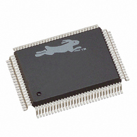
IC CPU RABBIT2000 30MHZ 100PQFP
Manufacturer
Rabbit Semiconductor
Datasheet
1.20-668-0003.pdf
(228 pages)
Specifications of 20-668-0003
Processor Type
Rabbit 2000 8-Bit
Speed
30MHz
Voltage
2.7V, 3V, 3.3V, 5V
Mounting Type
Surface Mount
Package / Case
100-MQFP, 100-PQFP
Data Bus Width
8 bit
Maximum Clock Frequency
30 MHz
Operating Supply Voltage
0 V to 5.5 V
Maximum Operating Temperature
+ 85 C
Mounting Style
SMD/SMT
Minimum Operating Temperature
- 40 C
Number Of Programmable I/os
40
Number Of Timers
8 & 10 bit
Lead Free Status / RoHS Status
Lead free / RoHS Compliant
Features
-
Lead Free Status / Rohs Status
Lead free / RoHS Compliant
Other names
20-668-0003
316-1062
316-1062
Available stocks
Company
Part Number
Manufacturer
Quantity
Price
Company:

Part Number:
20-668-0003
Manufacturer:
Rabbit Semiconductor
Quantity:
10 000


The control register (TACR) is laid out as shown in Table 11-3.
The time constant register for each timer is simply an 8-bit data register holding a number
between 0 and 255. The time constant registers are write only.
11.1.2 Practical Use of Timer A
Timer A is disabled (bit 0 in control and status register) on power-up. Timer A is normally
set up while the clock is disabled, but the timer setup can be changed while the timer is
running when there is a need to do so. Timers that are not used should be driven from the
output of A1 and the reload register should be set to 255. This will cause counting to be as
slow as possible and consume minimum power.
Timer A has five separate subtimer units, A1 and A4–A5, that are also referred to as timers.
Most likely, if a serial port is going to be used and a timer is needed to provide the baud
clock, that timer will be set up to be driven directly from the clock, and the interrupt asso-
ciated with that timer will be disabled. (Serial port interrupts are generated by the serial
port logic.)
The value in the reload register can be changed while the timer is running to change the
period of the next timer cycle. When the reload register is initialized, the contents of the
countdown counter may be unknown, for example, during power-up initialization. If inter-
rupts are enabled, then the first interrupt may take place at an unknown time. Similarly, if
the timer output is being used to drive the clock for a parallel port or serial port, the first
clock may come at a random time. If a periodic clock is desired, it is probably not impor-
tant when the first clock takes place unless a phase relationship is desired relative to a dif-
ferent timers.
A phase relationship between two timers can be obtained in several ways. One way is to
set both reload registers to zero and to wait long enough for both timers to reload (maxi-
mum 256 clocks). Then both timers’ reload registers can be set to new values before or
after both are clocked.
114
Source A7
0-pclk/2
1-A1
Bit 7
A7
Source A6
0-pclk/2
1-A1
Bit 6
A6
Table 11-3. Timer A Control Register (adr = 0x0A4)
Source A5
0-pclk/2
1-A1
Bit 5
A5
Source A4
0-pclk/2
1-A1
Bit 4
A4
not used
ignored
Bits 3, 2
Rabbit 2000 Microprocessor User’s Manual
00—Interrupt disabled
01—Enable priority 1 interrupt
10—Enable priority 2 interrupt
11—Enable priority 3 interrupt
Bits 1, 0
Related parts for 20-668-0003
Image
Part Number
Description
Manufacturer
Datasheet
Request
R

Part Number:
Description:
IC CPU RABBIT4000 128-LQFP
Manufacturer:
Rabbit Semiconductor
Datasheet:
Part Number:
Description:
IC MPU RABIT3000A 55.5MHZ128LQFP
Manufacturer:
Rabbit Semiconductor
Datasheet:

Part Number:
Description:
Microprocessors - MPU Rabbit 3000 TFBGA Microprocessor
Manufacturer:
Rabbit Semiconductor
Part Number:
Description:
Microprocessors - MPU Rabbit 4000 LQFP Microprocessor
Manufacturer:
Rabbit Semiconductor
Part Number:
Description:
IC, I/O EXPANDER, 8BIT, 40MHZ, TQFP-64
Manufacturer:
Rabbit Semiconductor

Part Number:
Description:
SCRs 1.5A 200uA 400V Sensing
Manufacturer:
Littelfuse Inc
Datasheet:

Part Number:
Description:
CARD 6-RELAY SMARTSTAR SR9500
Manufacturer:
Rabbit Semiconductor
Datasheet:

Part Number:
Description:
WIRE-BOARD CONN RECEPTACLE, 6POS, 3.96MM
Manufacturer:
TE Connectivity
Datasheet:
Part Number:
Description:
ADAPTER 20 PIN .420" PLUGS(6PCS)
Manufacturer:
Logical Systems Inc.
Datasheet:

Part Number:
Description:
CONN BARRIER BLOCK .438" 20 POS
Manufacturer:
Cinch Connectors
Datasheet:

Part Number:
Description:
20 MODII 2PC HDR DR SHRD, ROHS
Manufacturer:
TE Connectivity
Datasheet:

Part Number:
Description:
WIRE-BOARD CONN RECEPTACLE, 6POS, 3.96MM
Manufacturer:
TE Connectivity
Datasheet:


