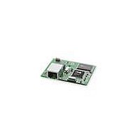
20-101-1112 Rabbit Semiconductor, 20-101-1112 Datasheet - Page 121

20-101-1112
Manufacturer Part Number
20-101-1112
Description
MODULE RABBITCORE RCM4010
Manufacturer
Rabbit Semiconductor
Datasheet
1.20-101-1094.pdf
(130 pages)
Specifications of 20-101-1112
Module/board Type
MPU Core Module
Product
Microcontroller Modules
Core Processor
Rabbit 4000
Clock Speed
58.98 MHz
Interface Type
Ethernet, Serial
Flash
512 KB
Timers
10 x 8 bit, 1 x 10 bit, 1 x 16 bit
Operating Supply Voltage
3 V to 3.6 V
Board Size
47 mm x 61 mm x 20 mm
Core
RCM4010
Processor Series
RCM4000
Silicon Manufacturer
Rabbit
Core Architecture
Rabbit 4000
Silicon Core Number
RCM4010
Silicon Family Name
RCM4000
Kit Contents
Board
Development Tool Type
Hardware / Software - Dev Kit (Dev Tool)
Rohs Compliant
Yes
For Use With/related Products
RCM4010
Lead Free Status / RoHS Status
Lead free / RoHS Compliant
Other names
Q3413688
- Current page: 121 of 130
- Download datasheet (809Kb)
C.1 Power Supplies
The RCM4000 requires a regulated 3.0 V – 3.6 V DC power source. The RabbitCore
design presumes that the voltage regulator is on the user board, and that the power is made
available to the RCM4000 board through header J2.
An RCM4000 with no loading at the outputs operating at 58.98 MHz typically draws
110 mA.
C.1.1 Battery Backup
The RCM4000 does not have a battery, but there is provision for a customer-supplied bat-
tery to back up the data SRAM and keep the internal Rabbit 4000 real-time clock running.
Header J2, shown in Figure C-1, allows access to the external battery. This header makes
it possible to connect an external 3 V power supply. This allows the SRAM and the inter-
nal Rabbit 4000 real-time clock to retain data with the RCM4000 powered down.
A lithium battery with a nominal voltage of 3 Vand a minimum capacity of 165 mA·h is
recommended. A lithium battery is strongly recommended because of its nearly constant
nominal voltage over most of its life. A minimum battery voltage of 2.5 V is required for
proper operation.
User’s Manual
Appendix C provides information on the current requirements of
the RCM4000, and includes some background on the chip select
circuit used in power management.
Figure C-1. External Battery Connections
A
PPENDIX
at Header J2
C. P
OWER
S
UPPLY
115
Related parts for 20-101-1112
Image
Part Number
Description
Manufacturer
Datasheet
Request
R

Part Number:
Description:
COMPUTER SGL-BRD BL2500 29.4MHZ
Manufacturer:
Rabbit Semiconductor
Datasheet:

Part Number:
Description:
COMPUTER SGL-BRD BL2500 29.4MHZ
Manufacturer:
Rabbit Semiconductor
Datasheet:

Part Number:
Description:
DISPLAY GRAPHIC 12KEY PROG OP670
Manufacturer:
Rabbit Semiconductor
Datasheet:

Part Number:
Description:
DISPLAY GRAPHIC 12KEY ETH OP6700
Manufacturer:
Rabbit Semiconductor
Datasheet:

Part Number:
Description:
COMPUTER SINGLE-BOARD BL2030
Manufacturer:
Rabbit Semiconductor

Part Number:
Description:
COMPUTER SGL-BOARD ETH BL2010
Manufacturer:
Rabbit Semiconductor

Part Number:
Description:
MODULE OP6810 W/O ETH/MEM EXPANS
Manufacturer:
Rabbit Semiconductor
Datasheet:

Part Number:
Description:
COMPUTER SINGLE-BOARD BL2020
Manufacturer:
Rabbit Semiconductor

Part Number:
Description:
COMPUTER BL2010 W/FRICTION LOCK
Manufacturer:
Rabbit Semiconductor

Part Number:
Description:
COMPUTER BL2020 W/FRICTION LOCK
Manufacturer:
Rabbit Semiconductor

Part Number:
Description:
COMPUTER SGL-BRD BL2500 44.2MHZ
Manufacturer:
Rabbit Semiconductor
Datasheet:

Part Number:
Description:
COMPUTER SGL-BOARD FULL BL2000
Manufacturer:
Rabbit Semiconductor

Part Number:
Description:
COMPUTER SINGLE-BOARD BL2110
Manufacturer:
Rabbit Semiconductor

Part Number:
Description:
COMPUTER SGL-BRD 29.4MHZ BL2610
Manufacturer:
Rabbit Semiconductor
Datasheet:

Part Number:
Description:
INTERFACE OP6800 512K FLASH&SRAM
Manufacturer:
Rabbit Semiconductor
Datasheet:


