20-101-1246 Rabbit Semiconductor, 20-101-1246 Datasheet - Page 20
20-101-1246
Manufacturer Part Number
20-101-1246
Description
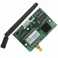
CORE MODULE RCM5400W
Manufacturer
Rabbit Semiconductor
Datasheet
1.20-101-1246.pdf
(120 pages)
Specifications of 20-101-1246
Module/board Type
MPU Core Module
Wireless Frequency
73.73 MHz
For Use With/related Products
RCM5400W
Lead Free Status / RoHS Status
Lead free / RoHS Compliant
Other names
316-1148


2.2.5 Step 5 — Connect Power
Once all the other connections have been made, you can connect power to the Prototyping
Board.
If you have the universal AC adapter, prepare the AC adapter for the country where it will
be used by selecting the appropriate plug. Snap in the top of the plug assembly into the slot
at the top of the AC adapter as shown in Figure 5, then press down on the plug until it
clicks into place.
Connect the AC adapter to 3-pin header J1 on the Prototyping Board as shown in Figure 5
above. The connector may be attached either way as long as it is not offset to one side—
the center pin of J1 is always connected to the positive terminal, and either edge pin is
ground.
Plug in the AC adapter. The
PWR
LED on the Prototyping Board next to the power con-
nector at J1 should light up. The RCM5400W and the Prototyping Board are now ready to
be used.
NOTE: A RESET button is provided on the Prototyping Board next to the battery holder
to allow a hardware reset without disconnecting power.
To power down the Prototyping Board, unplug the power connector from J1. You should
disconnect power before making any circuit adjustments in the prototyping area, changing
any connections to the board, or removing the RCM5400W from the Prototyping Board.
14
RabbitCore RCM5400W
Related parts for 20-101-1246
Image
Part Number
Description
Manufacturer
Datasheet
Request
R

Part Number:
Description:
COMPUTER SGL-BRD BL2500 29.4MHZ
Manufacturer:
Rabbit Semiconductor
Datasheet:

Part Number:
Description:
COMPUTER SGL-BRD BL2500 29.4MHZ
Manufacturer:
Rabbit Semiconductor
Datasheet:

Part Number:
Description:
DISPLAY GRAPHIC 12KEY PROG OP670
Manufacturer:
Rabbit Semiconductor
Datasheet:
Part Number:
Description:
DISPLAY GRAPHIC 12KEY ETH OP6700
Manufacturer:
Rabbit Semiconductor
Datasheet:

Part Number:
Description:
COMPUTER SINGLE-BOARD BL2030
Manufacturer:
Rabbit Semiconductor
Part Number:
Description:
COMPUTER SGL-BOARD ETH BL2010
Manufacturer:
Rabbit Semiconductor

Part Number:
Description:
MODULE OP6810 W/O ETH/MEM EXPANS
Manufacturer:
Rabbit Semiconductor
Datasheet:
Part Number:
Description:
COMPUTER SINGLE-BOARD BL2020
Manufacturer:
Rabbit Semiconductor
Part Number:
Description:
COMPUTER BL2010 W/FRICTION LOCK
Manufacturer:
Rabbit Semiconductor
Part Number:
Description:
COMPUTER BL2020 W/FRICTION LOCK
Manufacturer:
Rabbit Semiconductor
Part Number:
Description:
COMPUTER SGL-BRD BL2500 44.2MHZ
Manufacturer:
Rabbit Semiconductor
Datasheet:
Part Number:
Description:
COMPUTER SGL-BOARD FULL BL2000
Manufacturer:
Rabbit Semiconductor

Part Number:
Description:
COMPUTER SINGLE-BOARD BL2110
Manufacturer:
Rabbit Semiconductor

Part Number:
Description:
COMPUTER SGL-BRD 29.4MHZ BL2610
Manufacturer:
Rabbit Semiconductor
Datasheet:
Part Number:
Description:
INTERFACE OP6800 512K FLASH&SRAM
Manufacturer:
Rabbit Semiconductor
Datasheet: