20-101-1246 Rabbit Semiconductor, 20-101-1246 Datasheet - Page 100
20-101-1246
Manufacturer Part Number
20-101-1246
Description
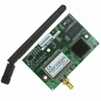
CORE MODULE RCM5400W
Manufacturer
Rabbit Semiconductor
Datasheet
1.20-101-1246.pdf
(120 pages)
Specifications of 20-101-1246
Module/board Type
MPU Core Module
Wireless Frequency
73.73 MHz
For Use With/related Products
RCM5400W
Lead Free Status / RoHS Status
Lead free / RoHS Compliant
Other names
316-1148


•
•
•
•
94
Analog Inputs Header
at header J3 on the Prototyping Board. These analog signals are connected via attenuator/
filter circuits on the Prototyping Board to the corresponding analog inputs on the Rabbit-
Core module.
RS-232
ing Board at header J4. A 10-pin 0.1" pitch header strip installed at J4 allows you to
connect a ribbon cable that leads to a standard DE-9 serial connector.
Current Measurement Option
bottom side of the Prototyping Board and install a 1 × 2 header strip from the Develop-
ment Kit to allow you to use an ammeter across the pins to measure the current drawn
from the +5 V supply. Similarly, you may cut the trace below header JP2 on the bottom
side of the Prototyping Board and install a 1 × 2 header strip from the Development Kit
to allow you to use an ammeter across the pins to measure the current drawn from the
+3.3 V supply.
Backup Battery
battery backup for the RCM5400W data SRAM and real-time clock.
NOTE: No analog signals are available on the Prototyping Board with the RCM5400W
RabbitCore module installed since no analog signals are available on the RCM5400W’s
header J1.
—Two 3-wire or one 5-wire RS-232 serial ports are available on the Prototyp-
—A 2032 lithium-ion battery rated at 3.0 V, 220 mA·h, provides
—The analog signals from a RabbitCore module are presented
—You may cut the trace below header JP1 on the
RabbitCore RCM5400W
Related parts for 20-101-1246
Image
Part Number
Description
Manufacturer
Datasheet
Request
R

Part Number:
Description:
COMPUTER SGL-BRD BL2500 29.4MHZ
Manufacturer:
Rabbit Semiconductor
Datasheet:

Part Number:
Description:
COMPUTER SGL-BRD BL2500 29.4MHZ
Manufacturer:
Rabbit Semiconductor
Datasheet:

Part Number:
Description:
DISPLAY GRAPHIC 12KEY PROG OP670
Manufacturer:
Rabbit Semiconductor
Datasheet:
Part Number:
Description:
DISPLAY GRAPHIC 12KEY ETH OP6700
Manufacturer:
Rabbit Semiconductor
Datasheet:

Part Number:
Description:
COMPUTER SINGLE-BOARD BL2030
Manufacturer:
Rabbit Semiconductor
Part Number:
Description:
COMPUTER SGL-BOARD ETH BL2010
Manufacturer:
Rabbit Semiconductor

Part Number:
Description:
MODULE OP6810 W/O ETH/MEM EXPANS
Manufacturer:
Rabbit Semiconductor
Datasheet:
Part Number:
Description:
COMPUTER SINGLE-BOARD BL2020
Manufacturer:
Rabbit Semiconductor
Part Number:
Description:
COMPUTER BL2010 W/FRICTION LOCK
Manufacturer:
Rabbit Semiconductor
Part Number:
Description:
COMPUTER BL2020 W/FRICTION LOCK
Manufacturer:
Rabbit Semiconductor
Part Number:
Description:
COMPUTER SGL-BRD BL2500 44.2MHZ
Manufacturer:
Rabbit Semiconductor
Datasheet:
Part Number:
Description:
COMPUTER SGL-BOARD FULL BL2000
Manufacturer:
Rabbit Semiconductor

Part Number:
Description:
COMPUTER SINGLE-BOARD BL2110
Manufacturer:
Rabbit Semiconductor

Part Number:
Description:
COMPUTER SGL-BRD 29.4MHZ BL2610
Manufacturer:
Rabbit Semiconductor
Datasheet:
Part Number:
Description:
INTERFACE OP6800 512K FLASH&SRAM
Manufacturer:
Rabbit Semiconductor
Datasheet: