9-1393792-7 TE Connectivity, 9-1393792-7 Datasheet - Page 86
9-1393792-7
Manufacturer Part Number
9-1393792-7
Description
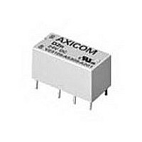
Electromechanical Relay DPDT 3A 12VDC 720Ohm Through Hole
Manufacturer
TE Connectivity
Type
Signal Relayr
Specifications of 9-1393792-7
Contact Arrangement
DPDT
Dc Coil Voltage
12 V
Coil Current
16.67 mA
Mounting
Through Hole
Relay Construction
Non-Latching
Coil Voltage Dc
12V
Contact Form
2 Form C
Voltage Rating (vdc)
220V
Voltage Rating (vac)
250V
Dropout Volt (min)
0.6VDCV
Coil Resistance
720Ohm
Pick-up Voltage (max)
8.4VDC
Maximum Power Rating
60W/125VA
Operate Time
5ms
Contact Current Rating
3A
Contact Material
AgNi/Au
Coil Suppression Diode
No
Push To Test Button
No
Led Indicator
No
Seal
Unsealed
Product Height (mm)
11mm
Product Depth (mm)
10mm
Product Length (mm)
20.2mm
Operating Temp Range
-25C to 85C
Pin Count
8
Mounting Style
Through Hole
Termination Style
PC Pin
Package / Case
DIP
Lead Free Status / Rohs Status
Compliant


314
Features
• Surface and through-hole mounting types.
• 1 Form C contact arrangement.
• Latching or non-latching versions available.
• Switches loads from dry circuit to 1 amp.
• Washable – meets IEC protection class IP67.
• Low coil power requirement for IC compatibility.
• Terminals arranged on 0.1” grid.
• Designed for compact, high density mounting, 106.6mm
• Ideal for data and communication systems.
Contact Data @ 23 C
Arrangements: 1 Form C (SPDT) bifurcated contacts.
Material & Style:Palladium-Nickel with Gold-Rhodium overlay.
Expected Mechanical Life: 1 billion operations.
Expected Electrical Life: 50 million ops. at 10mA, 12VDC;
Contact Ratings:
UL/CSA Contact Ratings:
Initial Contact Resistance: 50 milliohms max. @ 10mA, 20mV.
High Frequency Data
Capacitance: Between Open Contacts: 5pF, max.
RF Characteristics: Isolation at 100 / 900 MHz: -30.9 db / -18.0 db.
Initial Dielectric Strength
Between Open Contacts: 500V rms for 1 minute.
Between Contacts and Coil: 1,500V rms for 1 minute.
Surge Voltage Resistance per Bellcore TR-NWT-001089 (2 / 10 s):
Surge Voltage Resistance per FCC 68 (10 / 160 s):
Note: Consult factory regarding availability of models meeting high surge
Initial Insulation Resistance
Between Mutually Insulated Conductors: 10
Coil Data @ 23 C
Voltage: 1.5 to 24VDC.
Thermal Resistance at Continuous Thermal Load: 130 K per Watt.
Maximum Coil Temperature: 85 C.
Duty Cycle: Continuous.
Dimensions are shown for
reference purposes only.
Maximum Switched Voltage: 125VDC, 150VAC.
Maximum Switched Current: 1A.
Maximum Carrying Current: 1A.
Maximum Switched Power: 30W (DC), 60VA (AC).
Minimum Switched Capability: 100 V.
Between Open Contacts: 2,000V on request.
Between Coil and Contacts: 2,500V.
Between Open Contacts: 1,500V on request.
Between Coil and Contacts: 1,500V.
resistance requirements between open contacts.
Between Coil and Contacts: 6pF, max.
Insertion loss at 100 / 900 MHz: -0.12 db / -1.9 db.
V. S. W. R. at 100 / 900 MHz: 1.06 db / 1.75 db.
10 million ops. at 100mA, 6VDC;
100,000 ops. at 1A, 30VDC.
1A @ 30VDC;
460mA @ 65VDC;
460mA @ 150VAC.
Dimensions are in inches over
(millimeters) unless otherwise
specified.
9
ohms @ 500VDC.
2
surface area.
Catalog 1308242
Issued 3-03
V23026 (P1)
Miniature, Sealed
PC Board Relay
Users should thoroughly review the technical data before selecting a product part
number. It is recommended that user also seek out the pertinent approvals files of
the agencies/laboratories and review them to ensure the product meets the
requirements for a given application.
(1) The specified voltages apply with only one coil energized.
Environmental Data
Temperature Range: -40 C to +70 C.
Vibration, Operational: 40g, 10-200 Hz; 20g, 200-2000 Hz.
Shock, Operational: 50g at 11 ms 1/2 sinusoidal impulse.
Resistance to Soldering Heat: 260 C for 10s. Internal relay temperature
Needle Flame Test: Application time 20s, burning time <15s.
Coil Data @ 23 C
Mechanical Data
Termination: Through-hole or surface mount printed circuit terminals.
Enclosure Type: Immersion cleanable, plastic sealed case.
Weight: 0.063 oz. (1.8g) approximately.
Non-Latching — Through-Hole versions (A1)
Non-Latching — Surface-Mount versions (D1)
Bistable, Dual Coils — Through-Hole and Surface-Mount versions (B1,E1)
Bistable, Single Coil — Through-Hole and Surface-Mount versions (C1,F1)
Operate Data @ 23 C
Must Operate Voltage: 75% of nominal voltage or less.
Must Release Voltage: 10% of nominal voltage or less.
Max. Continuous Thermal Load : 500mW.
Operate Time (Excluding Bounce)†: 1 ms, typ.
Operate Bounce Time†: 1 ms, typ.
Release Time (Excluding Bounce)†: 0.4 ms, typ.
Set Time (Latching)†: 1 ms, typ.
Reset Time (Latching)†: 1 ms, typ.
Maximum Switching Rate: 200 operations/second.
† At or from Nominal Coil Voltage
Nominal
Voltage
(VDC)
12
15
24
12
15
24
12
15.
12
15.
24
File E48393
File LR45064-5
1.5
3
5
9
1.5
3
5
9
1.5
3
5
9
1.5
3
5
9
Specifications and availability
subject to change.
Voltage (VDC)
Maximum
Operating
14.5
25.5
35
42
50
13.3
24
32
40
50
14.75
14.75
29
29
13
20
35
50
50
50
8.8
8
4.25
8.55
4.5
4
6
(values are the same for each coil)
Nominal
Power
(mW)
128
128
150
128
should not exceed 210 C.
70
63
66
67
69
64
72
80
80
80
80
80
80
69
64
68
96
37
30
34
38
32
50
series
Resistance
(Ohms)
1,165
2,250
3,100
4,500
1,013
1,800
2,813
4,500
1,200
1,500
1,500
2,160
4,500
4,500
4,500
10%
137
370
113
313
130
390
300
740
36
28
32
61
(1)
www.tycoelectronics.com
Technical support:
Refer to inside back cover.
Order Designation
(Step 4 in Ordering
Information chart)
Coil Number
AXICOM
7
6
1
5
2
3
4
7
6
1
5
2
3
4
7
6
1
5
2
3
5
6
1
7
2
3
4
Related parts for 9-1393792-7
Image
Part Number
Description
Manufacturer
Datasheet
Request
R

Part Number:
Description:
CRIMP, RECEPTACLE
Manufacturer:
TE Connectivity
Datasheet:

Part Number:
Description:
PIGGYBACK DISCONNECT, 6.35MM, CRIMP BLUE
Manufacturer:
TE Connectivity
Datasheet:

Part Number:
Description:
Manufacturer:
TE Connectivity
Datasheet:

Part Number:
Description:
CRIMP TERMINAL, FEMALE, BLUE
Manufacturer:
TE Connectivity
Datasheet:
Part Number:
Description:
Manufacturer:
TE Connectivity
Datasheet:

Part Number:
Description:
CONN HEADR BRKWAY .100 13POS R/A
Manufacturer:
Tyco Electronics
Datasheet:
Part Number:
Description:
CONN HEADR BRKWAY .100 13POS R/A
Manufacturer:
Tyco Electronics
Datasheet:
Part Number:
Description:
CONN HDR BRKWAY .100 13POS VERT
Manufacturer:
Tyco Electronics
Datasheet:
Part Number:
Description:
CONN HDR BRKWAY .100 13POS VERT
Manufacturer:
Tyco Electronics
Datasheet:
Part Number:
Description:
CONN HDR BRKWAY .100 13POS VERT
Manufacturer:
Tyco Electronics
Datasheet:
Part Number:
Description:
CONN HEADR BRKWAY .100 13POS R/A
Manufacturer:
Tyco Electronics
Datasheet:
Part Number:
Description:
CONN HEADR BRKWAY .100 13POS STR
Manufacturer:
Tyco Electronics
Datasheet:
Part Number:
Description:
CONN HEADR BRKWAY .100 13POS STR
Manufacturer:
Tyco Electronics
Datasheet:
Part Number:
Description:
CONN HEADR BRKWAY .100 13POS STR
Manufacturer:
Tyco Electronics
Datasheet:
Part Number:
Description:
CONN HEADR BRKWAY .100 13POS R/A
Manufacturer:
Tyco Electronics
Datasheet: