9-1393792-7 TE Connectivity, 9-1393792-7 Datasheet - Page 212
9-1393792-7
Manufacturer Part Number
9-1393792-7
Description
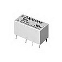
Electromechanical Relay DPDT 3A 12VDC 720Ohm Through Hole
Manufacturer
TE Connectivity
Type
Signal Relayr
Specifications of 9-1393792-7
Contact Arrangement
DPDT
Dc Coil Voltage
12 V
Coil Current
16.67 mA
Mounting
Through Hole
Relay Construction
Non-Latching
Coil Voltage Dc
12V
Contact Form
2 Form C
Voltage Rating (vdc)
220V
Voltage Rating (vac)
250V
Dropout Volt (min)
0.6VDCV
Coil Resistance
720Ohm
Pick-up Voltage (max)
8.4VDC
Maximum Power Rating
60W/125VA
Operate Time
5ms
Contact Current Rating
3A
Contact Material
AgNi/Au
Coil Suppression Diode
No
Push To Test Button
No
Led Indicator
No
Seal
Unsealed
Product Height (mm)
11mm
Product Depth (mm)
10mm
Product Length (mm)
20.2mm
Operating Temp Range
-25C to 85C
Pin Count
8
Mounting Style
Through Hole
Termination Style
PC Pin
Package / Case
DIP
Lead Free Status / Rohs Status
Compliant


504
Contact Ratings @ 25 C with relay properly vented. Remove vent
nib after soldering and cleaning.
Features
• Up to 30A switching in SPST and 20A switching in SPDT arrangements.
• Silver cadmium oxide contacts.
• Available as an open-frame relay, with a snap-on dust cover or with an
• Meets UL 508 & UL 873 spacing – 1/8” through air, 1/8” over surface.
• UL class F insulation standard.
• Well suited for various industrial, commercial and residential applications,
Contact Ratings @ 25 C
Arrangements: 1 Form A (SPST-NO) and 1 Form C (SPDT).
Material: Silver-cadmium oxide.
Mechanical Life: 10 million operations, typical.
Typical Electrical Load & Life (Open Style Relay)
Form & Contact Material
Initial Dielectric Strength
Between Open Contacts: 1,500V rms.
Between Contacts and Coil: 1,500V rms ( terminal code 1).
Initial Insulation Resistance
Between Mutually Insulated Elements: 10
Coil Data @ 25 C
Voltage: 5 to 110VDC.
Maximum Coil Power: 2.8 Watt
Maximum Coil Temperature
Duty Cycle: Continuous.
Coil Data
Operate Data @ 25 C
Must Operate Voltage: 75% of nominal voltage or less.
Must Release Voltage: 10% of nominal voltage or more.
Operate Time (Including Bounce)†: 15 ms, max.
Release Time (Including Bounce)†: 15 ms, max.
† At or From Nominal Coil Voltage
Minimum Contact Load:
Initial Contact Resistance: 75 m , max., @ min. rated current (switched).
Dimensions are shown for
reference purposes only.
Nominal Voltage
immersion cleanable
(1/4” over surface with terminal code 4)
as well as many others.
Silver Contacts: 500mA @ 5VDC or 12VAC.
Silver Cadmium Oxide Contacts: 1A @ 5VDC or 12VAC.
(1) Silver-cadmium
(5) Silver-cadmium
(VDC)
110
oxide
oxide
12
15
18
24
48
5
6
9
(6)
Resistance
10% (Ohms)
, plastic sealed case.
13,450
20A/10A @ 240VAC UL General Purpose
2,560
20A/10A @ 28VDC
155
256
380
660
30A @ 240VAC
20A @ 240VAC
Contact Load
27
40
97
(5)
2,500V rms (UL 873 version terminal code 4).
: Class F: 155 C.
Nominal Power
25 C and 50% R.H.
Dimensions are in inches over
(millimeters) unless otherwise
specified.
(mW)
9
UL General Purpose
930
900
840
930
880
850
870
900
900
ohms, min., @ 500VDC,
Resistive Heater
Type of Load
Resistive
Nominal Current
(mA)
185
150
93
77
59
47
36
19
100,000
100,000
100,000
100,000
8
Ops
Catalog 1308242
Issued 3-03
Notes
(1) Operating ambient temperature must consider “Must Operate Voltage Change
(2) Sealed relay terminals should not be bent.
(3) Knock-off nib should be removed after cleaning process for optimum life of
(4) Maximum soldering temperature is 500 F for 4 seconds.
(5) Class F coils are UL systems approved for maximum coil temperature of
(6) See application note 13C265 for proper relay mounting, termination, cleaning
T90
30 Amp Printed Circuit Board Relay
Users should thoroughly review the technical data before selecting a product part
number. It is recommended that user also seek out the pertinent approvals files of
the agencies/laboratories and review them to ensure the product meets the
requirements for a given application.
Typical Coil Temperature Rise
Data below are average values and should be verified in application. Tests
were conducted within a 2’ (.6 m) cube (still air) with relay mounted to a
30A, single side P.C. board
open contact loaded; and with 4’ (1.22 m) long, #10 AWG load wires.
Environmental Data
Storage Temperature Range: -40 C to 130 C.
Operating Temperature Range: -55 C to +85 C
Vibration, Operational: 0.065” (1.65mm) max. excursions from 10-55 Hz.
Shock, Operational: 10g for 11 ms with no contact opening >100 s.
Shock, Mechanical: 100g.
Mechanical Data
Termination: Printed circuit terminals
Enclosures (all have 94V-0 flammability rating, Class F temp. rating):
Weight: Open Model T90N: 0.7 oz. (20g) approximately.
Optional dust cover: Snap-on plastic dust cover is available for use on
Sealed case (T90S): Immersion cleanable, sealed plastic case
130
120
110
100
150
140
130
120
110
100
Over Temperature,” Contact Temperature Rise, Coil Temperature Rise (If coil
is not allowed to cool) and Maximum Coil Temperature. Specification ambient
considers nominal coil voltage, 20A load with coil cooled to ambient.
sealed relays.
155 C by change of resistance method.
and PC board conductor width. Coil rise test performed with 30A PC board to
maintain 20 C maximum rise @ 30A.
90
80
70
60
50
40
30
20
90
80
70
60
50
40
30
20
File E22575
Patented
50
50
30A Load
25A Load
20A Load
15A Load
10A Load
0A Load
30A Load
25A Load
20A Load
15A Load
10A Load
0A Load
Specifications and availability
subject to change.
Open Style Relay, No Dust Cover
Sealed Relay, Vented
Sealed Model T90S: 0.9 oz. (26g) approximately.
series
Applied Continuous Coil Voltage (% of Rated Voltage)
Applied Continuous Coil Voltage (% of Rated Voltage)
75
75
100
100
open style T90N.
with no contact opening >100 s.
(3)
(6)
; at nominal coil power @ 25 C; with normally
125
125
File LR15734
(4)
150
150
.
175
175
(1)
.
www.tycoelectronics.com
Technical support:
Refer to inside back cover.
200
200
(2)
225
225
.
P&B
Related parts for 9-1393792-7
Image
Part Number
Description
Manufacturer
Datasheet
Request
R

Part Number:
Description:
CRIMP, RECEPTACLE
Manufacturer:
TE Connectivity
Datasheet:

Part Number:
Description:
PIGGYBACK DISCONNECT, 6.35MM, CRIMP BLUE
Manufacturer:
TE Connectivity
Datasheet:

Part Number:
Description:
Manufacturer:
TE Connectivity
Datasheet:

Part Number:
Description:
CRIMP TERMINAL, FEMALE, BLUE
Manufacturer:
TE Connectivity
Datasheet:
Part Number:
Description:
Manufacturer:
TE Connectivity
Datasheet:

Part Number:
Description:
CONN HEADR BRKWAY .100 13POS R/A
Manufacturer:
Tyco Electronics
Datasheet:
Part Number:
Description:
CONN HEADR BRKWAY .100 13POS R/A
Manufacturer:
Tyco Electronics
Datasheet:
Part Number:
Description:
CONN HDR BRKWAY .100 13POS VERT
Manufacturer:
Tyco Electronics
Datasheet:
Part Number:
Description:
CONN HDR BRKWAY .100 13POS VERT
Manufacturer:
Tyco Electronics
Datasheet:
Part Number:
Description:
CONN HDR BRKWAY .100 13POS VERT
Manufacturer:
Tyco Electronics
Datasheet:
Part Number:
Description:
CONN HEADR BRKWAY .100 13POS R/A
Manufacturer:
Tyco Electronics
Datasheet:
Part Number:
Description:
CONN HEADR BRKWAY .100 13POS STR
Manufacturer:
Tyco Electronics
Datasheet:
Part Number:
Description:
CONN HEADR BRKWAY .100 13POS STR
Manufacturer:
Tyco Electronics
Datasheet:
Part Number:
Description:
CONN HEADR BRKWAY .100 13POS STR
Manufacturer:
Tyco Electronics
Datasheet:
Part Number:
Description:
CONN HEADR BRKWAY .100 13POS R/A
Manufacturer:
Tyco Electronics
Datasheet: