9-1393792-7 TE Connectivity, 9-1393792-7 Datasheet - Page 405
9-1393792-7
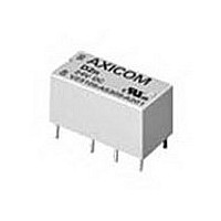
Manufacturer Part Number
9-1393792-7
Description
Electromechanical Relay DPDT 3A 12VDC 720Ohm Through Hole
Manufacturer
TE Connectivity
Type
Signal Relayr
Specifications of 9-1393792-7
Contact Arrangement
DPDT
Dc Coil Voltage
12 V
Coil Current
16.67 mA
Mounting
Through Hole
Relay Construction
Non-Latching
Coil Voltage Dc
12V
Contact Form
2 Form C
Voltage Rating (vdc)
220V
Voltage Rating (vac)
250V
Dropout Volt (min)
0.6VDCV
Coil Resistance
720Ohm
Pick-up Voltage (max)
8.4VDC
Maximum Power Rating
60W/125VA
Operate Time
5ms
Contact Current Rating
3A
Contact Material
AgNi/Au
Coil Suppression Diode
No
Push To Test Button
No
Led Indicator
No
Seal
Unsealed
Product Height (mm)
11mm
Product Depth (mm)
10mm
Product Length (mm)
20.2mm
Operating Temp Range
-25C to 85C
Pin Count
8
Mounting Style
Through Hole
Termination Style
PC Pin
Package / Case
DIP
Lead Free Status / Rohs Status
Compliant


Dimensions are shown for
reference purposes only.
AGASTAT Time Delay Relay Timing Modes
On-Delay: Time delay is initiated upon application of a control signal (i.e.,
operating voltage or on 11-pin model closure of the control switch). The output
contacts energize at the end of the delay. Output contacts and the time delay
circuit reset upon removal of the control signal regardless of state.
Off-Delay: The output contacts energize when the control switch is closed.
The time delay is initiated upon opening of the control switch (operating
voltage is applied continuously). De-energization occurs at the end of the
delay. Output contacts energize and the time delay circuit resets upon closure
of the control switch.
Interval: Time delay is initiated upon application of a control signal (i.e.,
operating voltage or closure of the control switch on 11-pin models). The
output contacts energize when the control signal is applied. At the end of the
delay, the output contacts de-energize. Output contacts and the time delay
circuit reset upon removal of the control signal regardless of state.
On / Interval : Time delay 1 is initiated upon application of a control signal (i.e.,
operating voltage or closure of the control switch on 11-pin models). The
output contacts energize at the end of time delay 1 and de-energize at the end
of time delay 2. Output contacts and the time delay circuit reset upon removal
of the control signal regardless of state. Note: For the 48K series, delay 2 is
fixed at 0.5 seconds.
Note: When an external control switch is used, it must
be closed before the unit is energized. If external
control switch is open, the unit will not time out.
OPERATING VOLTAGE/
CONTROL SWITCH
OUTPUT
CONTACTS
OPERATING VOLTAGE/
CONTROL SWITCH
OUTPUT
CONTACTS
OPERATING VOLTAGE/
CONTROL SWITCH
OUTPUT
CONTACTS
OPERATING
VOLTAGE
CONTROL
SWITCH
OUTPUT
CONTACTS
ON / CLOSED
ON / CLOSED
ENERGIZED
ENERGIZED
ON / CLOSED
ENERGIZED
OFF / OPEN
OFF / OPEN
ENERGIZED
OFF / OPEN
DE-ENER.
DE-ENER.
DE-ENER.
CLOSED
DE-ENER.
OPEN
OFF
ON
DELAY 1
DELAY
DELAY
Dimensions are in inches over
(millimeters) unless otherwise
specified.
DELAY
DELAY 2
Catalog 1308242
Issued 3-03
On-Delay / Off-Delay: Time delay is initiated for delay 1 upon closure of the
control switch, for delay 2 upon opening of the control switch. (Operating
voltage is applied continuously.) Output contacts energize at the end of time
delay 1, and de-energize at the end of time delay 2. If the control state is
reversed during the time delay, the time delay circuit automatically resets to
zero. Note: For the 48K series, time delays 1 and 2 are identical.
Repeat Cycle: Application of the operating voltage starts time delay 1. Upon
expiration of this delay, the output contacts energize. Time delay 2 begins
simultaneously. At the end of time delay 2, the output contacts de-energize,
and a new cycle begins. The cycles continue until power is removed. To reset
the timer, input voltage must be removed. The state of the output contacts
may be reversed on the 11-pin 48K by closing the control switch. Note: For the
48K series, the time delays are identical.
Accumulating On-Delay: Time delay is initiated upon closure of the control
switch. (Operating voltage is applied continuously.) Energization of the output
contacts occurs at the end of the delay. If the control switch is opened during
the time delay, the time delay pauses, and the relay holds (remembers) the
delay accumulated so far. The time delay resumes when the control switch
is re-closed. After energization, reset by opening the control switch. Regard-
less of state, reset by removing the operating voltage.
One Shot (Latching Interval): Operating voltage must be applied continu-
ously. Output contacts energize and time delay is initiated upon closure of the
control switch. Once closed, state of control switch has no further influence
until time delay has expired. Upon expiration of time delay, output contacts de-
energize and timer is reset by opening the control switch.
Specifications and availability
subject to change.
OPERATING
VOLTAGE
OUTPUT
CONTACTS
OPERATING
VOLTAGE
CONTROL
SWITCH
OUTPUT
CONTACTS
OPERATING
VOLTAGE
CONTROL
SWITCH
OUTPUT
CONTACTS
OPERATING
VOLTAGE
CONTROL
SWITCH
OUTPUT
CONTACTS
ENERGIZED
ENERGIZED
DE-ENER.
ENERGIZED
ENERGIZED
DE-ENER.
DE-ENER.
CLOSED
DE-ENER.
CLOSED
CLOSED
OPEN
OFF
OPEN
ON
OFF
OPEN
ON
OFF
OFF
ON
ON
DELAY
1
DELAY ACCUMULATION
DELAY 1
DELAY
DELAY
2
OFF AT
ANY TIME
DELAY
DELAY 2
1
www.tycoelectronics.com
Technical support:
Refer to inside back cover.
DELAY
2
AGASTAT
1205
Related parts for 9-1393792-7
Image
Part Number
Description
Manufacturer
Datasheet
Request
R

Part Number:
Description:
CRIMP, RECEPTACLE
Manufacturer:
TE Connectivity
Datasheet:

Part Number:
Description:
PIGGYBACK DISCONNECT, 6.35MM, CRIMP BLUE
Manufacturer:
TE Connectivity
Datasheet:

Part Number:
Description:
Manufacturer:
TE Connectivity
Datasheet:

Part Number:
Description:
CRIMP TERMINAL, FEMALE, BLUE
Manufacturer:
TE Connectivity
Datasheet:
Part Number:
Description:
Manufacturer:
TE Connectivity
Datasheet:

Part Number:
Description:
CONN HEADR BRKWAY .100 13POS R/A
Manufacturer:
Tyco Electronics
Datasheet:
Part Number:
Description:
CONN HEADR BRKWAY .100 13POS R/A
Manufacturer:
Tyco Electronics
Datasheet:
Part Number:
Description:
CONN HDR BRKWAY .100 13POS VERT
Manufacturer:
Tyco Electronics
Datasheet:
Part Number:
Description:
CONN HDR BRKWAY .100 13POS VERT
Manufacturer:
Tyco Electronics
Datasheet:
Part Number:
Description:
CONN HDR BRKWAY .100 13POS VERT
Manufacturer:
Tyco Electronics
Datasheet:
Part Number:
Description:
CONN HEADR BRKWAY .100 13POS R/A
Manufacturer:
Tyco Electronics
Datasheet:
Part Number:
Description:
CONN HEADR BRKWAY .100 13POS STR
Manufacturer:
Tyco Electronics
Datasheet:
Part Number:
Description:
CONN HEADR BRKWAY .100 13POS STR
Manufacturer:
Tyco Electronics
Datasheet:
Part Number:
Description:
CONN HEADR BRKWAY .100 13POS STR
Manufacturer:
Tyco Electronics
Datasheet:
Part Number:
Description:
CONN HEADR BRKWAY .100 13POS R/A
Manufacturer:
Tyco Electronics
Datasheet: