9-1393792-7 TE Connectivity, 9-1393792-7 Datasheet - Page 466
9-1393792-7
Manufacturer Part Number
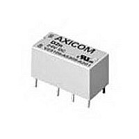
9-1393792-7
Description
Electromechanical Relay DPDT 3A 12VDC 720Ohm Through Hole
Manufacturer
TE Connectivity
Type
Signal Relayr
Specifications of 9-1393792-7
Contact Arrangement
DPDT
Dc Coil Voltage
12 V
Coil Current
16.67 mA
Mounting
Through Hole
Relay Construction
Non-Latching
Coil Voltage Dc
12V
Contact Form
2 Form C
Voltage Rating (vdc)
220V
Voltage Rating (vac)
250V
Dropout Volt (min)
0.6VDCV
Coil Resistance
720Ohm
Pick-up Voltage (max)
8.4VDC
Maximum Power Rating
60W/125VA
Operate Time
5ms
Contact Current Rating
3A
Contact Material
AgNi/Au
Coil Suppression Diode
No
Push To Test Button
No
Led Indicator
No
Seal
Unsealed
Product Height (mm)
11mm
Product Depth (mm)
10mm
Product Length (mm)
20.2mm
Operating Temp Range
-25C to 85C
Pin Count
8
Mounting Style
Through Hole
Termination Style
PC Pin
Package / Case
DIP
Lead Free Status / Rohs Status
Compliant


1310
WD2759 Specifications
Nominal Operating Range: 120, 208, 277 or 480 VAC, selectable.
Maximum Sensing Range: 700VAC.
Nominal Frequency Range: 50-400 Hz.
Contact Form: 1 form C (SPDT) for undervoltage and 1 form C (SPDT) for
overvoltage.
Time Delay Adjustment: 0.5 to 10 sec.
Sense Voltage:
Control Voltage:
Ordering Information
Our authorized distributor is more likely to stock these items.
WD2759 Typical Hookup
WD2759 Operation
WD2759 AC voltage sensing relays provide voltage monitoring and protection
in AC systems from 50 to 400 Hz. Sensing voltages, number of phases, over
and undervoltage setpoint, and time delays are user configured. WD2759
voltage relays operate when the externally adjustable trip point is reached. An
external time delay control is provided with an adjustment of .5 to 10 seconds.
This time delay may be used to prevent false tripping when there are slight
variations in the voltage supply.
energizes when the input signal exceeds the trip point. On undervoltage (UV)
the output relay de-energizes when the input signal goes below the trip point.
A green LED indicates power to the relay. Red LED lights indicate the state
of the undervoltage and overvoltage trips.
WD2759-003.
Dimensions are shown for
reference purposes only.
Voltage (nominal)
UV Adjustment Range
OV Adjustment Range
Model WD2759
Input Voltage (VDC)
Input Voltage (VAC)
1. Basic Series:
2. Type:
3. Control Voltage:
WD = DIN mount Protective Relay.
2759 = Over/Undervoltage Relay.
001 = 18 to 54VDC
002 = 13.5 to 32 VDC
003 = 100-200VDC or 100-140VAC.
Typical Part Number
120-168
72-120
B
18 to 54
120
On overvoltage (OV) the output relay
-001
–
Dimensions are in inches over
(millimeters) unless otherwise
specified.
125-208
208-291
208
13.5 to 32
WD 2759 -002
-002
–
166-277
277-388
277
100 to 200
100 to 140
288-480
480-672
-003
480
Catalog 1308242
Issued 3-03
WD2759 Calibration
The calibration marks on the faceplate have a maximum error of 10% and
are provided only as guides. Proper calibration requires using an accurate
voltmeter in parallel with the input signal. Use the following procedure to
calibrate your relay.
OVER VOLTAGE
1. Remove cover.
2. Adjust the TRIP SET control fully clockwise (CW) and the TIME DELAY
3. Apply the desired trip voltage to the relay.
4. Slowly adjust the TRIP SET control CCW until the relay trips.
5. Remove the applied voltage (do not change the voltage level) and set
6. Apply the trip voltage to the relay and measure the time to trip.
7. Adjust the TIME DELAY and repeat steps 4 and 5 until you have the
UNDER VOLTAGE
1. Remove cover.
2. Adjust the TRIP SET control fully CCW and the TIME DELAY control fully
3. Decrease the applied sensing voltage from the nominal value until the
4. Slowly adjust the TRIP SET control CW until the relay trips.
5. Set the TIME DELAY control to the desired time delay and apply
6. Step down the applied voltage from nominal to a level jest below the
7. Adjust the TIME DELAY and repeat steps 4 and 5 until the desired time
WD2759 Controls
WD2759 Over/Undervoltage Relays
• Function 27/59
• ANSI/IEEE C37.90-1978
control fully counterclockwise (CCW).
the TIME DELAY control to the desired time delay.
desired time delay.
CCW.
desired tripping voltage is reached.
nominal voltage to the relay.
trip level set in Step 3 and measure the time delay.
delay is achieved.
Specifications and availability
subject to change.
WD2759 Connections
www.tycoelectronics.com
Technical support:
Refer to inside back cover.
KILOVAC
Related parts for 9-1393792-7
Image
Part Number
Description
Manufacturer
Datasheet
Request
R

Part Number:
Description:
CRIMP, RECEPTACLE
Manufacturer:
TE Connectivity
Datasheet:

Part Number:
Description:
PIGGYBACK DISCONNECT, 6.35MM, CRIMP BLUE
Manufacturer:
TE Connectivity
Datasheet:

Part Number:
Description:
Manufacturer:
TE Connectivity
Datasheet:

Part Number:
Description:
CRIMP TERMINAL, FEMALE, BLUE
Manufacturer:
TE Connectivity
Datasheet:
Part Number:
Description:
Manufacturer:
TE Connectivity
Datasheet:

Part Number:
Description:
CONN HEADR BRKWAY .100 13POS R/A
Manufacturer:
Tyco Electronics
Datasheet:
Part Number:
Description:
CONN HEADR BRKWAY .100 13POS R/A
Manufacturer:
Tyco Electronics
Datasheet:
Part Number:
Description:
CONN HDR BRKWAY .100 13POS VERT
Manufacturer:
Tyco Electronics
Datasheet:
Part Number:
Description:
CONN HDR BRKWAY .100 13POS VERT
Manufacturer:
Tyco Electronics
Datasheet:
Part Number:
Description:
CONN HDR BRKWAY .100 13POS VERT
Manufacturer:
Tyco Electronics
Datasheet:
Part Number:
Description:
CONN HEADR BRKWAY .100 13POS R/A
Manufacturer:
Tyco Electronics
Datasheet:
Part Number:
Description:
CONN HEADR BRKWAY .100 13POS STR
Manufacturer:
Tyco Electronics
Datasheet:
Part Number:
Description:
CONN HEADR BRKWAY .100 13POS STR
Manufacturer:
Tyco Electronics
Datasheet:
Part Number:
Description:
CONN HEADR BRKWAY .100 13POS STR
Manufacturer:
Tyco Electronics
Datasheet:
Part Number:
Description:
CONN HEADR BRKWAY .100 13POS R/A
Manufacturer:
Tyco Electronics
Datasheet: