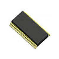
IDTV386GLFT IDT, Integrated Device Technology Inc, IDTV386GLFT Datasheet - Page 6

IDTV386GLFT
Manufacturer Part Number
IDTV386GLFT
Description
Manufacturer
IDT, Integrated Device Technology Inc
Datasheet
1.IDTV386GLFT.pdf
(10 pages)
Specifications of IDTV386GLFT
Number Of Elements
4
Number Of Receivers
4
Number Of Drivers
24
Operating Supply Voltage (typ)
3.3V
Differential Input High Threshold Voltage
100mV
Diff. Input Low Threshold Volt
-100mV
Operating Supply Voltage (min)
3V
Operating Supply Voltage (max)
3.6V
Operating Temp Range
-10C to 70C
Operating Temperature Classification
Commercial
Mounting
Surface Mount
Pin Count
56
Lead Free Status / Rohs Status
Compliant
V386 Datasheet
I DT • 2 0 6 4 S i l v e r C r e ek Va l l e y R o a d, S a n J os e , CA 9 5 1 3 8 • t e l ( 8 0 0 ) 3 4 5 - 7 0 1 5 • w w w. i dt . c o m
Note: The skew margins mean the maximum timing tolerance between the clock and data channel when the
receiver still works well. This margin takes into account the receiver input setup and hold time, and internal clock
jitter (i.e., internal data sampling window - RSPos). This margin allows for LVDS transmitter pulse position,
interconnect skew, inter-symbol interference and intrinsic channel mismatch which will cause the skew between
clock (RC+ and RCK-) and data (RX[n]+ and RX[n]- ; n =0, 1, 2, 3) channels.
Thermal Characteristics
Receiver Input Strobe Position for
Bit5
Receiver Input Strobe Position for
Bit6
RxIn Skew Margin (see note and
Figure 8)
Thermal Resistance Junction to Ambient
Thermal Resistance Junction to Case
V386
8-B
Parameter
IT
Parameter
LVDS R
ECEIVER FOR
Symbol
RSPos5
RSPos6
Rskm
V
Symbol
IDEO
f = 85 MHz, T = 11.76 ns
f = 85 MHz, T = 11.76 ns
f = 85 MHz, T = 11.76 ns
f = 65 MHz, T = 15.38 ns
θ
θ
θ
θ
JC
JA
JA
JA
6
Still air
1 m/s air flow
3 m/s air flow
Conditions
Conditions
10.57
Min.
Min.
8.89
300
500
10.92
Typ.
9.24
Typ.
84
76
67
50
7/5/07
Max.
11.27
Max.
9.59
Revision 2.2
Units
° C/W
° C/W
° C/W
° C/W
Units
ns
ns
ps
ps


