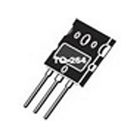
APT33GF120LRD MICROSEMI, APT33GF120LRD Datasheet - Page 5

APT33GF120LRD
Manufacturer Part Number
APT33GF120LRD
Description
Manufacturer
MICROSEMI
Datasheet
1.APT33GF120LRD.pdf
(8 pages)
Specifications of APT33GF120LRD
Channel Type
N
Configuration
Single
Collector-emitter Voltage
1.2kV
Gate To Emitter Voltage (max)
±20V
Pin Count
3 +Tab
Mounting
Through Hole
Operating Temperature (max)
150C
Operating Temperature Classification
Military
Lead Free Status / Rohs Status
Not Compliant
Available stocks
Company
Part Number
Manufacturer
Quantity
Price
Company:
Part Number:
APT33GF120LRD
Manufacturer:
APT
Quantity:
15 500
MAXIMUM RATINGS (FRED)
STATIC ELECTRICAL CHARACTERISTICS (FRED)
V
I
A
B
C
2
1
C
Symbol
Symbol
IF
IF
I
FSM
V
V
V
90%
10%
L
RMS
AV
CE
GE
S
F
t
(off)
(off)
d
(on)
Characteristic
Maximum Average Forward Current (T
RMS Forward Current
Non-Repetive Forward Surge Current (T
Characteristic / Test Conditions
Maximum Forward Voltage
Series Inductance (Lead to Lead 5mm from Base)
90%
10%
t
t
d
r
(on)
10%
V
V
t
C
r
GE
(on)
V
CE
I
(on)
Figure 16, Resistive Switching Time Test Circuit and Waveforms
C
t
d
(off)
E
V
on
Figure 15, Switching Loss Test Circuit and Waveforms
CE
D.U.T.
t
(SAT)
d
(off)
90%
C
t
t=2uS
f
J
= 100°C, Duty Cycle = 0.5)
= 45°C, 8.3 ms)
t
f
I
I
I
F
F
F
= 30A
= 60A
= 30A, T
E
off
90%
10%
J
= 150°C
All Ratings: T
Gate Drive
Circuitry
From
V
CHARGE
100uH
A
DRIVER*
A
C
= 25°C unless otherwise specified.
MIN
33GF120B2RD/LRD
*DRIVER SAME TYPE AS D.U.T.
V
E
R
CC
t s
G
= E
APT33GF120B2RD/LRD
= 0.66 V
V
210
TYP
on
2.0
30
70
CLAMP
10
+ E
1
I
C
CES
off
MAX
V
2.5
2.0
V
C
CC
D.U.T.
R
L
D.U.T.
=
2
Amps
UNIT
UNIT
Volts
.5 V
nH
B
I
C2
CES
R
G


