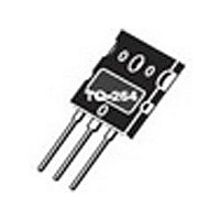
APT33GF120LRD MICROSEMI, APT33GF120LRD Datasheet - Page 4

APT33GF120LRD
Manufacturer Part Number
APT33GF120LRD
Description
Manufacturer
MICROSEMI
Datasheet
1.APT33GF120LRD.pdf
(8 pages)
Specifications of APT33GF120LRD
Channel Type
N
Configuration
Single
Collector-emitter Voltage
1.2kV
Gate To Emitter Voltage (max)
±20V
Pin Count
3 +Tab
Mounting
Through Hole
Operating Temperature (max)
150C
Operating Temperature Classification
Military
Lead Free Status / Rohs Status
Not Compliant
Available stocks
Company
Part Number
Manufacturer
Quantity
Price
Company:
Part Number:
APT33GF120LRD
Manufacturer:
APT
Quantity:
15 500
Figure 12, Typical Switching Energy Losses vs. Junction Temperature
Figure 8, Typical V
Figure 10, Breakdown Voltage vs Junction Temperature
100
4.0
2.0
1.5
1.0
1.2
1.1
0.9
0.8
0.7
0.1
5.0
20
10
1
1
1
-50 -25
-50 -25
-50 -25
0.1
V
CC
V
T
T
R
T
GE
= 0.66 V
G
J
J
J
, JUNCTION TEMPERATURE (°C)
, JUNCTION TEMPERATURE (°C)
, JUNCTION TEMPERATURE (°C)
= 10
= +15V
CE
0
0
0
CES
(SAT) Voltage vs Junction Temperature
25
25
25
0.5 I
0.5 I
50
50
50
I
I
I
I
C1
C2
C1
C2
C2
C2
75
75
75 100 125 150
1.0
100 125 150
100 125 150
Figure 14,Typical Load Current vs Frequency
F, FREQUENCY (KHz)
10
Figure 13, Typical Switching Energy Losses vs Collector Current
Figure 11, Typical Switching Energy Losses vs Gate Resistance
Figure 9, Maximum Collector Current vs Case Temperature
60
40
20
16
12
0
8
4
0
4
3
2
1
0
25
0
0
V
V
I
C
CC
CC
V
V
T
, COLLECTOR CURRENT (AMPERES)
T
R
J
GE
GE
J
I
= 0.66 V
= 0.66 V
C
G
R
= +125°C
= +25°C
T
= I
G
= 10
= +15V
= +15V
20
C
50
, GATE RESISTANCE (OHMS)
, CASE TEMPERATURE (°C)
C2
10
CES
CES
100
E
off
40
75
E
on
E
E
20
off
on
I
LOAD
Power dissapation = 83W
Gate drive as specified
100
60
Duty Cycle = 50%
APT33GF120B2RD/LRD
T
= I
T
sink
J
RMS
For Both:
= +125°C
= +90°C
of fundamental
30
125
80
1000
100
150
40


