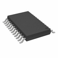
AD7739BRU Analog Devices Inc, AD7739BRU Datasheet - Page 22

AD7739BRU
Manufacturer Part Number
AD7739BRU
Description
IC ADC 24BIT 8-CH 24-TSSOP
Manufacturer
Analog Devices Inc
Datasheet
1.AD7739BRUZ.pdf
(32 pages)
Specifications of AD7739BRU
Rohs Status
RoHS non-compliant
Number Of Bits
24
Sampling Rate (per Second)
15.1k
Data Interface
DSP, MICROWIRE™, QSPI™, Serial, SPI™
Number Of Converters
1
Power Dissipation (max)
100mW
Voltage Supply Source
Analog and Digital
Operating Temperature
-40°C ~ 105°C
Mounting Type
Surface Mount
Package / Case
24-TSSOP (0.173", 4.40mm Width)
For Use With
EVAL-AD7739EBZ - BOARD EVAL FOR AD7739
Available stocks
Company
Part Number
Manufacturer
Quantity
Price
Company:
Part Number:
AD7739BRUZ
Manufacturer:
ADI
Quantity:
1 000
Company:
Part Number:
AD7739BRUZ
Manufacturer:
Analog Devices Inc
Quantity:
1 859
Part Number:
AD7739BRUZ
Manufacturer:
ADI/亚德诺
Quantity:
20 000
Company:
Part Number:
AD7739BRUZ-REEL7
Manufacturer:
ADI
Quantity:
1 000
AD7739
DIGITAL INTERFACE DESCRIPTION
HARDWARE
The AD7739 serial interface can be connected to the host device
via the serial interface in several different ways.
The CS pin can be used to select the AD7739 as one of several
circuits connected to the host serial interface. When CS is high,
the AD7739 ignores the SCLK and DIN signals and the DOUT
pin goes to the high impedance state. When the CS signal is not
used, connect the CS pin to DGND.
The RDY pin can be polled for high-to-low transition or can
drive the host device interrupt input to indicate that the
AD7739 has finished the selected operation and/or new data
from the AD7739 is available. The host system can also wait a
designated time after a given command is written to the device
before reading. Alternatively, the AD7739 status can be polled.
When the RDY pin is not used in the system, it should be left as
an open circuit. (Note that the RDY pin is always an active
digital output, i.e., it never goes into a high impedance state.)
Figure 14. AD7739 to Host Device Interface, DSP
Figure 13. AD7739 to Host Device Interface, SPI
AD7739
AD7739
RESET
DOUT
SCLK
RESET
RDY
DOUT
SCLK
DIN
CS
RDY
DIN
CS
DV
DGND
DV
DD
DD
DV
DD
ADSP-2105
SCLK
DR
DT
INT
TFS
RFS
68HC11
SS
SCK
MISO
MOSI
INT
03742-0-013
03742-0-001
Rev. 0 | Page 22 of 32
The RESET pin can be used to reset the AD7739. When not
used, connect this pin to DV
The AD7739 interface can be reduced to just two wires
connecting the DIN and DOUT pins to a single bidirectional
data line. The second signal in this 2-wire configuration is the
SCLK signal. The host system should change the data line
direction with reference to the AD7739 timing specification
(see the Bus Relinquish Time in Table 2). The AD7739 cannot
operate in the continuous read mode in 2-wire serial interface
configuration.
All the digital interface inputs are Schmitt triggered; therefore,
the AD7739 interface features higher noise immunity and can
be easily isolated from the host system via optocouplers.
Figure 13, Figure 14, and Figure 15 outline some of the possible
host device interfaces: SPI without using the CS signal
(Figure 13), a DSP interface (Figure 14), and a 2-wire
configuration (Figure 15).
Figure 15. AD7739 to Host Device Interface, 2-Wire Configuration
Figure 16. Serial Interface Signals—Registers Access
DOUT
SCLK
AD7739
DIN
CS
RESET
DOUT
SCLK
COMMUNICATIONS
DIN
CS
REGISTER
WRITE
DGND
DV
DD
DD
.
ADC STATUS
REGISTER
P3.1/TxD
P3.0/RxD
READ
8xC51
03742-0-016
03742-0-015


