AD7715ANZ-3 Analog Devices Inc, AD7715ANZ-3 Datasheet - Page 10
AD7715ANZ-3
Manufacturer Part Number
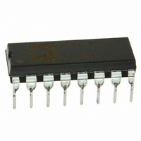
AD7715ANZ-3
Description
IC ADC 16BIT SIGMA-DELTA 16DIP
Manufacturer
Analog Devices Inc
Specifications of AD7715ANZ-3
Data Interface
DSP, MICROWIRE™, QSPI™, Serial, SPI™
Number Of Bits
16
Sampling Rate (per Second)
500
Number Of Converters
1
Power Dissipation (max)
9.5mW
Voltage Supply Source
Analog and Digital
Operating Temperature
-40°C ~ 85°C
Mounting Type
Through Hole
Package / Case
16-DIP (0.300", 7.62mm)
Resolution (bits)
16bit
Input Channel Type
Differential
Supply Voltage Range - Analogue
3V To 3.6V
Supply Voltage Range - Digital
3V To 5.25V
Supply Current
600µA
No. Of
RoHS Compliant
Sampling Rate
19.2kSPS
Rohs Compliant
Yes
Lead Free Status / RoHS Status
Lead free / RoHS Compliant
For Use With
EVAL-AD7715-3EBZ - BOARD EVALUATION FOR AD7715
Lead Free Status / RoHS Status
Lead free / RoHS Compliant
Available stocks
Company
Part Number
Manufacturer
Quantity
Price
Company:

Part Number:
AD7715ANZ-3
Manufacturer:
INFINEON
Quantity:
12
Part Number:
AD7715ANZ-3
Manufacturer:
ADI/亚德诺
Quantity:
20 000


AD7715
Setup Register (RS1, RS0 = 0, 1); Power On/Reset Status: 28 Hex
The Setup Register is an eight-bit register from which data can either be read or to which data can be written. This register controls
the setup which the device is to operate in such as the calibration mode, output rate, unipolar/bipolar operation etc. Table III out-
lines the bit designations for the Setup Register.
MD1
0
0
1
1
CLK
FS1, FS0
MD0
0
1
0
1
MD1
Operating Mode
Normal Mode; this is the normal mode of operation of the device whereby the device is performing normal
conversions. This is the default condition of these bits after Power-On or RESET.
Self-Calibration; this activates self-calibration on the part. This is a one step calibration sequence and when
complete the part returns to Normal Mode with MD1 and MD0 returning to 0, 0. The DRDY output or bit
goes high when calibration is initiated and returns low when this self-calibration is complete and a new valid
word is available in the data register. The zero-scale calibration is performed at the selected gain on internally
shorted (zeroed) inputs and the full-scale calibration is performed at the selected gain on an internally
generated V
Zero-Scale System Calibration; this activates zero-scale system calibration on the part. Calibration is per-
formed at the selected gain on the input voltage provided at the analog input during this calibration sequence.
This input voltage should remain stable for the duration of the calibration. The DRDY output or bit goes
high when calibration is initiated and returns low when this zero-scale calibration is complete and a new valid
word is available in the data register. At the end of the calibration, the part returns to Normal Mode with
MD1 and MD0 returning to 0, 0.
Full-Scale System Calibration; this activates full-scale system calibration on the part. Calibration is per-
formed at the selected gain on the input voltage provided at the analog input during this calibration sequence.
This input voltage should remain stable for the duration of the calibration. Once again, the DRDY output or
bit goes high when calibration is initiated and returns low when this full-scale calibration is complete and a
new valid word is available in the data register. At the end of the calibration, the part returns to Normal
Mode with MD1 and MD0 returning to 0, 0.
Clock Bit. This bit should be set in accordance with the operating frequency of the AD7715. If the device has
a master clock frequency of 2.4576 MHz, then this bit should be set to a 1. If the device has a master clock
frequency of 1 MHz, then this bit should be set to a 0. This bit sets up the correct scaling currents for a given
master clock and also chooses (along with FS1 and FS0) the output update rate for the device. If this bit is
not set correctly for the master clock frequency of the device, then the device may not operate to specifica-
tion. The default value for this bit after power-on or RESET is 1.
Filter Selection Bits. Along with the CLK bit, FS1 and FS0 determine the output update rate, filter first
notch and –3 dB frequency as outlined in Table IV. The on-chip digital filter provides a Sinc
filter response. In association with the gain selection, it also determines the output noise (and hence the
resolution) of the device. Changing the filter notch frequency, as well as the selected gain, impacts resolution.
Tables V through XII show the effect of the filter notch frequency and gain on the output noise and effective
resolution of the part. The output data rate (or effective conversion time) for the device is equal to the fre-
quency selected for the first notch of the filter. For example, if the first notch of the filter is selected at 50 Hz
then a new word is available at a 50 Hz rate or every 20 ms. If the first notch is at 500 Hz, a new word is
available every 2 ms. The default value for these bits is 1, 0.
The settling-time of the filter to a full-scale step input change is worst case 4 1/(output data rate). For
example, with the first filter notch at 50 Hz, the settling time of the filter to a full-scale step input change is
80 ms max. If the first notch is at 500 Hz, the settling time of the filter to a full-scale input step is 8 ms max.
This settling-time can be reduced to 3 1/(output data rate) by synchronizing the step input change to a
reset of the digital filter. In other words, if the step input takes place with the FSYNC bit high, the settling-
time time will be 3
The –3 dB frequency is determined by the programmed first notch frequency according to the relationship:
MD0
REF
/Selected Gain.
1/(output data rate) from when FSYNC returns low.
filter –3 dB frequency = 0.262 filter first notch frequency.
CLK
Table III. Setup Register
FS1
–10–
FS0
B/U
BUF
FSYNC
3
(or (Sinx/x)
REV. C
3
)
Related parts for AD7715ANZ-3
Image
Part Number
Description
Manufacturer
Datasheet
Request
R

Part Number:
Description:
±1.7g Dual-Axis IMEMS Accelerometer Evaluation Board
Manufacturer:
Analog Devices Inc
Datasheet:

Part Number:
Description:
Inertial Sensor Evaluation System
Manufacturer:
Analog Devices Inc
Datasheet:
Part Number:
Description:
Manufacturer:
Analog Devices Inc
Datasheet:
Part Number:
Description:
Manufacturer:
Analog Devices Inc
Datasheet:
Part Number:
Description:
Manufacturer:
Analog Devices Inc
Datasheet:
Part Number:
Description:
Manufacturer:
Analog Devices Inc
Datasheet:
Part Number:
Description:
Manufacturer:
Analog Devices Inc
Datasheet:
Part Number:
Description:
Manufacturer:
Analog Devices Inc
Datasheet:
Part Number:
Description:
Manufacturer:
Analog Devices Inc
Datasheet:
Part Number:
Description:
Manufacturer:
Analog Devices Inc
Datasheet:
Part Number:
Description:
Manufacturer:
Analog Devices Inc
Datasheet:
Part Number:
Description:
Manufacturer:
Analog Devices Inc
Datasheet:
Part Number:
Description:
Manufacturer:
Analog Devices Inc
Datasheet: