5-353293-2 TE Connectivity, 5-353293-2 Datasheet - Page 6
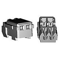
5-353293-2
Manufacturer Part Number
5-353293-2
Description
MINI CT MT REC ASSY 2P BLUE
Manufacturer
TE Connectivity
Specifications of 5-353293-2
Product Type
Connector
Connector Type
Connector Assembly
Termination Method To Wire/cable
IDC
Sealed
No
Ul File Number
E28476
Csa File Number
LR 7189-133
Contact - Rated Current (a)
2
Operating Voltage Reference
AC/DC, AC, DC
Operating Voltage (vac)
50
Operating Voltage (vdc)
50
Wire/cable Size (awg)
26 – 28
Profile Height (y-axis) (mm [in])
6.00 [0.236]
Number Of Positions
2
Number Of Rows
1
Centerline (mm [in])
1.50 [0.059]
Mating Retention
With
Length (x-axis) (mm [in])
4.50 [0.1772]
Width (z-axis) (mm [in])
3.60 [0.141]
Contact Type
Socket
Contact Plating, Mating Area, Material
Pre-Tin
Contact Plating, Mating Area, Thickness (µm [?in])
0.2 [7.87]
Contact Design
Dual Beam
Mating Alignment
With
Housing Color
Blue
Ul Flammability Rating
UL 94V-0
Rohs/elv Compliance
RoHS compliant, ELV compliant
Lead Free Solder Processes
Not relevant for lead free process
Rohs/elv Compliance History
Always was RoHS compliant
Agency/standard
UL, CSA
Operating Temperature (°c [°f])
-30 – +105 [-22 – +221]
Applies To
Wire/Cable
Accepts Wire Insulation Diameter, Range (mm [in])
0.80 – 0.95 [0.030 – 0.037]
Application Use
Wire-to-Board, Wire-to-Board / Wire-to-Wire / Wire-to-Panel, Wire-to-Panel, Wire-to-Wire
Contact Transmits (typical Application)
Signal (Data)
Pick And Place Cover
Without
Packaging Method
Bag, Box


ASHL-0005- ES REV B
3.8.13 Vibration
3.8.14 Physical Shock
3.8.15 Hammerring Shocks
3.8.16 Solderability
Para.
(Low Frequency)
Test Items
AMP Shanghai Ltd.
Tyco Electronics
No electrical discontinuity
greater than 1 µsec. Shall occur.
20 mΩ Max. (Final)
No electrical discontinuity
greater than 1µsec. Shall occur.
20 mΩ Max.(Final)
No electrical discontinuity
greater than 1µsec.shall occur.
20 mΩ Max.(Final)
Wet Solder Coverage :
90 % Min.
Fig. 2 (To be continued)
Requirements
6 of 17
PAGE
Document No.
108-5525
Subject mated connectors to 10-55-10
Hz traversed in 1 minute at 1.52 mm
amplitude 2 hours each of 3 mutually
perpendicular planes.
10 mA applied.
MIL-STD-202 TEST METHOD 201
CONDITION A
IEC 68-2-6
Mounting : Fig. 9
Accelerated Velocity :
490 m/s
Waveform: halfsine shock pulse
Duration : 11 msec.
Number of Drops : 3 drops each to
normal and reversed directions of X,
Y and Z axes, totally 18 drops. 10
mA DC applied.
MIL-STD-202 TEST METHOD 213
CONDITION A
IEC 68-2-27
Mounting : Fig. 9
Under 10000 cycles of repeated
hammering shocks of the condition as
shown Fig.10,with the test current of
1mA at 10VDC applied to the circuit
as shown in Fig.11.
During the test, the circuit shall be
monitored for fluctuation of electrical
resistance.
Solder Temperature : 230 ± 5 °C
Immersion Duration :3 ± 0.5 seconds
Flux : Alpha 100
(NON-active rosin base)
2
( 50 G)
Procedures
REV
A
LOC
ES
Related parts for 5-353293-2
Image
Part Number
Description
Manufacturer
Datasheet
Request
R

Part Number:
Description:
FASTIN-FASTON RECEP 6,35
Manufacturer:
TE Connectivity
Datasheet:

Part Number:
Description:
FASTIN-FASTON RECEP 6,35
Manufacturer:
TE Connectivity
Datasheet:

Part Number:
Description:
IC DELAY LINE 5TAP 35NSMAX 8SOIC
Manufacturer:
Maxim Integrated Products
Datasheet:

Part Number:
Description:
FASTIN-FASTON RECEP 6,35
Manufacturer:
TE Connectivity
Datasheet:

Part Number:
Description:
5-Tap Silicon Delay Line
Manufacturer:
Maxim Integrated Products

Part Number:
Description:
Conn Shrouded Header HDR 5 POS 2.54mm Solder ST Thru-Hole
Manufacturer:
TE Connectivity
Datasheet:

Part Number:
Description:
Conn Shrouded Header HDR 3 POS 2.54mm Solder RA Thru-Hole Tube
Manufacturer:
TE Connectivity
Datasheet:

Part Number:
Description:
Conn Shrouded Header HDR 4 POS 2.54mm Solder ST Thru-Hole Tube
Manufacturer:
TE Connectivity
Datasheet:

Part Number:
Description:
Conn Shrouded Header HDR 4 POS 2.54mm Solder ST Thru-Hole Tube
Manufacturer:
TE Connectivity
Datasheet:

Part Number:
Description:
Conn Shrouded Header HDR 4 POS 2.54mm Solder ST Thru-Hole Tube
Manufacturer:
TE Connectivity
Datasheet:

Part Number:
Description:
CAT3 MODULAR PLUG, 6POS, 1 PORT
Manufacturer:
TE Connectivity
Datasheet:

Part Number:
Description:
CAT3 RJ45 MODULAR PLUG, 8POS, 1 PORT
Manufacturer:
TE Connectivity
Datasheet:
Part Number:
Description:
CAT3 RJ45 MODULAR PLUG, 8POS, 1 PORT
Manufacturer:
TE Connectivity
Datasheet:

Part Number:
Description:
CAT3 MODULAR PLUG, 4POS, 1 PORT
Manufacturer:
TE Connectivity
Datasheet:

Part Number:
Description:
CAT3 RJ45 MODULAR PLUG, 8POS, 1 PORT
Manufacturer:
TE Connectivity
Datasheet: