5-353293-2 TE Connectivity, 5-353293-2 Datasheet - Page 5
5-353293-2
Manufacturer Part Number
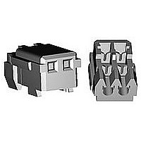
5-353293-2
Description
MINI CT MT REC ASSY 2P BLUE
Manufacturer
TE Connectivity
Specifications of 5-353293-2
Product Type
Connector
Connector Type
Connector Assembly
Termination Method To Wire/cable
IDC
Sealed
No
Ul File Number
E28476
Csa File Number
LR 7189-133
Contact - Rated Current (a)
2
Operating Voltage Reference
AC/DC, AC, DC
Operating Voltage (vac)
50
Operating Voltage (vdc)
50
Wire/cable Size (awg)
26 – 28
Profile Height (y-axis) (mm [in])
6.00 [0.236]
Number Of Positions
2
Number Of Rows
1
Centerline (mm [in])
1.50 [0.059]
Mating Retention
With
Length (x-axis) (mm [in])
4.50 [0.1772]
Width (z-axis) (mm [in])
3.60 [0.141]
Contact Type
Socket
Contact Plating, Mating Area, Material
Pre-Tin
Contact Plating, Mating Area, Thickness (µm [?in])
0.2 [7.87]
Contact Design
Dual Beam
Mating Alignment
With
Housing Color
Blue
Ul Flammability Rating
UL 94V-0
Rohs/elv Compliance
RoHS compliant, ELV compliant
Lead Free Solder Processes
Not relevant for lead free process
Rohs/elv Compliance History
Always was RoHS compliant
Agency/standard
UL, CSA
Operating Temperature (°c [°f])
-30 – +105 [-22 – +221]
Applies To
Wire/Cable
Accepts Wire Insulation Diameter, Range (mm [in])
0.80 – 0.95 [0.030 – 0.037]
Application Use
Wire-to-Board, Wire-to-Board / Wire-to-Wire / Wire-to-Panel, Wire-to-Panel, Wire-to-Wire
Contact Transmits (typical Application)
Signal (Data)
Pick And Place Cover
Without
Packaging Method
Bag, Box


ASHL-0005- ES REV B
3.8.6
3.8.7
3.8.8
3.8.9
3.8.10 Panal Retention Force
3.8.11 Connector Mating
3.8.12 Durability
Para.
Tensile Strength of
wire Termination
Post Retention Force
Contact Retention
Force
Panel Mounting Force
(To be applied to post
header relay panel
mount type)
(To be applied to post
header relay panel
mount type)
/Unmating Force
(Repeated Mate /
Unmating)
Test Items
AMP Shanghai Ltd.
Tyco Electronics
9.8 N(1.0 kgf) Min.
4.9 N(0.5 kgf) Min.
49 N(5 kgf ) MAX.
83.3 N(8.5 kgf) Min.
See Fig.12
20 mΩ Max. (Final)
(AWG)
Wire
Size
26
28
Mechanical Requirements
Fig. 2 (To be continued)
Requirements
Tensile Strength of Wire
Direction
19.6(2.0)
14.7(1.5)
N(kgf)
Axial
5 of 17
Termination(min.)
PAGE
Direction
11.8(1.2)
Traverse
Document No.
N(kgf)
108-5525
Apply a pull-off load to
terminated wire of contact
secured on the tester,
Operation Speed : 50 mm/min.
The load is applied in (1) the
axial and (2) the traverse
directions as specified.
Fig.5
Measure post retention force.
Operation Speed : 50 mm/min.
Fig.6
Apply an axial pull-off load to
crimped wire.
Operation Speed : 50 mm/min.
Measure panel retention force
using panel of nominal cut-out
dimensions as specified in the
drawing.
Loading is made from the
punch entering direction of the
cut-out hole.See Fig.7
Measure panel retention force
using panel of nominal cut-out
dimensions as specified in the
drawing.
Loading is made from the
punch entering direction of the
cut-out hole.See Fig.8
Operation Speed : 50 mm/min.
Measure the force required to
mate and unmate connectors.
Operation Speed : 50 mm/min.
No. of Cycles : 30 cycles.
Procedures
REV
A
LOC
ES
Related parts for 5-353293-2
Image
Part Number
Description
Manufacturer
Datasheet
Request
R

Part Number:
Description:
FASTIN-FASTON RECEP 6,35
Manufacturer:
TE Connectivity
Datasheet:

Part Number:
Description:
FASTIN-FASTON RECEP 6,35
Manufacturer:
TE Connectivity
Datasheet:

Part Number:
Description:
IC DELAY LINE 5TAP 35NSMAX 8SOIC
Manufacturer:
Maxim Integrated Products
Datasheet:

Part Number:
Description:
FASTIN-FASTON RECEP 6,35
Manufacturer:
TE Connectivity
Datasheet:

Part Number:
Description:
5-Tap Silicon Delay Line
Manufacturer:
Maxim Integrated Products

Part Number:
Description:
Conn Shrouded Header HDR 5 POS 2.54mm Solder ST Thru-Hole
Manufacturer:
TE Connectivity
Datasheet:

Part Number:
Description:
Conn Shrouded Header HDR 3 POS 2.54mm Solder RA Thru-Hole Tube
Manufacturer:
TE Connectivity
Datasheet:

Part Number:
Description:
Conn Shrouded Header HDR 4 POS 2.54mm Solder ST Thru-Hole Tube
Manufacturer:
TE Connectivity
Datasheet:

Part Number:
Description:
Conn Shrouded Header HDR 4 POS 2.54mm Solder ST Thru-Hole Tube
Manufacturer:
TE Connectivity
Datasheet:

Part Number:
Description:
Conn Shrouded Header HDR 4 POS 2.54mm Solder ST Thru-Hole Tube
Manufacturer:
TE Connectivity
Datasheet:

Part Number:
Description:
CAT3 MODULAR PLUG, 6POS, 1 PORT
Manufacturer:
TE Connectivity
Datasheet:

Part Number:
Description:
CAT3 RJ45 MODULAR PLUG, 8POS, 1 PORT
Manufacturer:
TE Connectivity
Datasheet:
Part Number:
Description:
CAT3 RJ45 MODULAR PLUG, 8POS, 1 PORT
Manufacturer:
TE Connectivity
Datasheet:

Part Number:
Description:
CAT3 MODULAR PLUG, 4POS, 1 PORT
Manufacturer:
TE Connectivity
Datasheet:

Part Number:
Description:
CAT3 RJ45 MODULAR PLUG, 8POS, 1 PORT
Manufacturer:
TE Connectivity
Datasheet: