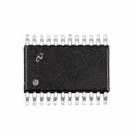
LMX2352TMX/NOPB National Semiconductor, LMX2352TMX/NOPB Datasheet - Page 15

LMX2352TMX/NOPB
Manufacturer Part Number
LMX2352TMX/NOPB
Description
IC FREQ SYNTHESIZER DUAL 24TSSOP
Manufacturer
National Semiconductor
Series
PLLatinum™r
Type
PLL Frequency Synthesizerr
Datasheet
1.LMX2352TMNOPB.pdf
(21 pages)
Specifications of LMX2352TMX/NOPB
Pll
Yes with Bypass
Input
CMOS, TTL
Output
CMOS
Number Of Circuits
1
Ratio - Input:output
3:3
Differential - Input:output
Yes/No
Frequency - Max
1.2GHz, 550MHz
Divider/multiplier
Yes/No
Voltage - Supply
2.7 V ~ 5.5 V
Operating Temperature
-40°C ~ 85°C
Mounting Type
Surface Mount
Package / Case
24-TSSOP
Frequency-max
1.2GHz
Lead Free Status / RoHS Status
Lead free / RoHS Compliant
Other names
LMX2352TMX
LMX2352TMXTR
LMX2352TMXTR
Available stocks
Company
Part Number
Manufacturer
Quantity
Price
Company:
Part Number:
LMX2352TMX/NOPB
Manufacturer:
ST
Quantity:
7 600
Programming Description
4.1.2 3-BIT IF SWALLOW COUNTER DIVIDE RATIO (IF A COUNTER)
Note: Swallow Counter Value: 0 to 7
4.1.3 12-BIT IF PROGRAMMABLE COUNTER DIVIDE RATIO (IF B COUNTER)
Note: Divide ratio: 3 to 4095 (Divide ratios less than 3 are prohibited)
4.2 RF_N Register
If the control bits (CTL[2:0]) are 11, data is transferred from the 24-bit shift register into the RF_N register latch which sets the RF
PLL 19 bit programmable N counter register and various control functions. The RF N counter consists of the 5-bit swallow counter
(A counter) the 10 bit programmable counter (B counter), and 4 bit fractional counter. Serial data format is shown below. The
divide ratio (RF_NB_CNTR) must be 3, and must be
4.2.1.1 RF_CTL_WORD
4.2.1.2 RF/IF Control Word Truth Table
The Counter Reset enable bit when activated allows the
reset of both N and R counters. Upon powering up, the N
counter resumes counting in ’close’ alignment with the R
counter (the maximum error is one prescaler cycle).
Activation of the PLL power down bits result in the disabling
of the respective N counter divider and de-biasing of its
respective fin inputs (to a high impedance state). The re-
spective R counter functionality also becomes disabled
when the power down bit is activated. The OSCin pin reverts
to a high impedance state when both RF and IF power down
bits are asserted. Power down forces the respective charge
IF_CNT_RST/RF_CNT_RST
PWDN_IF/PWDN_RF
PWDN_MODE
PRESC
MSB
RF_CTL_WORD [2:0]
23
Divide Ratio
IF_NB_CNTR
Minimum continuous count = 56 ( A=0, B=7)
IF_NB_CNTR
N divider continuous integer divide ratio 56 to 32,767.
4,095
3
4
-
Swallow Count
MSB
RF_CNT_RST
BIT
IF_NA_CNTR
IF_NA_CNTR
(A)
LMX2350
LMX2352
0
1
7
-
11
0
0
1
-
21
RF_NB_CNTR [9:0]
20
10
0
0
1
-
(RF_N[21]-[23])
IF/RF counter reset
IF/RF power down
Power down mode select
Prescaler Modulus select
9
0
0
1
-
FUNCTION
(Continued)
8
0
0
1
-
11
2
0
0
1
-
IF_NB_CNTR
the swallow counter value + 2; RF_NB_CNTR ( RF_NA_CNTR+2).
PWDN_RF
RF_NA_CNTR [4:0]
10
7
0
0
1
-
15
(0.5 to 1.2 GHz operation)
8/9
(0.25 to 0.5 GHz operation)
Normal Operation
Powered up
Asynchronous power down
16/17
pump and phase comparator logic to a TRI-STATE condition.
The MICROWIRE control register remains active and ca-
pable of loading and latching in data during all of the power
down modes.
Both synchronous and asynchronous power down modes
are available with the LMX2350 family in order to adapt to
different types of applications. The power down mode bit
IF_N[21] is used to select between synchronous and asyn-
chronous power down. The MICROWIRE control register
remains active and capable of loading and latching in data
during all of the power down modes.
6
0
0
1
-
IF_NA_CNTR
5
0
0
1
-
0
6
(IF_N[2]−[4])
1
0
0
1
-
4
0
0
1
-
FRAC_CONT [3:0]
5
(IF_N[5]-[16])
3
0
0
1
-
Reset
Powered down
Synchronous power down
32/33
(1.2 to 2.5 GHz operation)
16/17
(0.5 to 1.2 GHz operation)
PRESC_SEL
2
0
1
1
-
LSB
2
1
0
0
1
1
-
1
1
0
1
-
1
1
www.national.com
LSB
0
1
0
1
-
1
0


