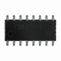
FS6377-01IG-XTD ON Semiconductor, FS6377-01IG-XTD Datasheet - Page 4

FS6377-01IG-XTD
Manufacturer Part Number
FS6377-01IG-XTD
Description
IC CLOCK GEN 3-PLL PROGR 16-SOIC
Manufacturer
ON Semiconductor
Type
PLL Clock Generatorr
Datasheet
1.FS6377-01G-XTD.pdf
(24 pages)
Specifications of FS6377-01IG-XTD
Pll
Yes
Input
Crystal
Output
CMOS
Number Of Circuits
1
Ratio - Input:output
1:4
Differential - Input:output
No/No
Frequency - Max
230MHz
Divider/multiplier
Yes/No
Voltage - Supply
3 V ~ 5.5 V
Operating Temperature
-40°C ~ 85°C
Mounting Type
Surface Mount
Package / Case
16-SOIC (3.9mm Width)
Frequency-max
230MHz
Number Of Elements
3
Pll Input Freq (min)
5MHz
Pll Input Freq (max)
27MHz
Operating Supply Voltage (typ)
3.3/5V
Operating Temp Range
-40C to 85C
Package Type
SOIC
Output Frequency Range
0.8 to 150MHz
Operating Supply Voltage (min)
3V
Operating Supply Voltage (max)
5.5V
Operating Temperature Classification
Industrial
Pin Count
16
Mounting Style
SMD/SMT
Number Of Outputs
1
Operating Temperature Range
0 C to + 70 C
Supply Current
43 mA
Lead Free Status / RoHS Status
Lead free / RoHS Compliant
Other names
766-1027
Available stocks
Company
Part Number
Manufacturer
Quantity
Price
Company:
Part Number:
FS6377-01IG-XTD
Manufacturer:
ON Semiconductor
Quantity:
135
Company:
Part Number:
FS6377-01IG-XTD
Manufacturer:
Exar
Quantity:
40
FS6377
For example, a fixed divide-by-eight could be used in the feedback divider. Unfortunately, a divide-by-eight would limit the effective
modulus of the entire feedback divider to multiples of eight. This limitation would restrict the ability of the PLL to achieve a desired input-
frequency-to-output frequency ratio without making both the reference and feedback divider values comparatively large.
A large feedback modulus means that the divided VCO frequency is relatively low, requiring a wide loop bandwidth to permit the low
frequencies. A narrow loop bandwidth tuned to high frequencies is essential to minimizing jitter; therefore, divider moduli should always
be as small as possible.
To understand the operation, refer to Figure 4. The M-counter (with a modulus always equal to M) is cascaded with the dual-modulus
prescaler. The A-counter controls the modulus of the prescaler. If the value programmed into the A-counter is A, the prescaler will be
set to divide by N+1 for A prescaler outputs. Thereafter, the prescaler divides by N until the M-counter output resets the A-counter, and
the cycle begins again. Note that N=8 and A and M are binary numbers.
Suppose that the A-counter is programmed to zero. The modulus of the prescaler will always be fixed at N; and the entire modulus of
the feedback divider becomes MxN.
Next, suppose that the A-counter is programmed to a one. This causes the prescaler to switch to a divide-by-N+1 for its first divide
cycle and then revert to a divide-by-N. In effect, the A-counter absorbs (or "swallows") one extra clock during the entire cycle of the
feedback divider. The overall modulus is now seen to be equal to MxN+1.
This example can be extended to show that the feedback divider modulus is equal to MxN+A, where A<M.
3.1.3. Feedback Divider Programming
For proper operation of the feedback divider, the A-counter must be programmed only for values that are less than or equal to the M-
counter. Therefore, not all divider moduli below 56 are available for use. The selection of divider values is listed in Table 2.
Above a modulus of 56, the feedback divider can be programmed to any value up to 2047.
Table 2: Feedback Divider Modulus Under 56
M-Counter:
FBKDIV[10:3]
00000001
00000010
00000011
00000100
00000101
00000110
00000111
000
8
16
24
32
40
48
56
001
9
17
25
33
41
49
57
010
18
26
34
42
50
58
Rev. 4 | Page 4 of 24 | www.onsemi.com
Figure 4: Feedback Divider
Feedback Divider Modulus
011
27
35
43
51
59
A-Counter: FBKDIV[2:0]
100
36
44
52
60
101
45
53
61
110
54
62
111
63


