ICS97U877AHLF IDT, Integrated Device Technology Inc, ICS97U877AHLF Datasheet
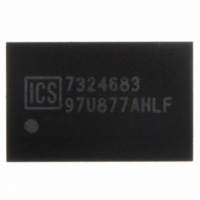
IC CLK DVR PLL 1:10 370MHZ 52BGA

ICS97U877AHLF

Manufacturer Part Number
ICS97U877AHLF
Description
IC CLK DVR PLL 1:10 370MHZ 52BGA
Manufacturer
IDT, Integrated Device Technology Inc
Type
Driver, PLLr
Datasheet

Specifications of ICS97U877AHLF

Pll
Yes with Bypass
Input
Clock
Output
SSTL-18
Number Of Circuits
1
Ratio - Input:output
1:10
Differential - Input:output
Yes/Yes
Frequency - Max
370MHz
Divider/multiplier
No/No
Voltage - Supply
1.7 V ~ 1.9 V
Operating Temperature
0°C ~ 70°C
Mounting Type
Surface Mount
Package / Case
52-BGA
Frequency-max
370MHz
Lead Free Status / RoHS Status
Lead free / RoHS Compliant
Other names
800-1236
97U877AHLF

Available stocks

Company
Part Number
Manufacturer
Quantity
Price
Part Number:
ICS97U877AHLF
Manufacturer:
ICS
Quantity:
4 192
Part Number:
ICS97U877AHLF
Manufacturer:
IDT, Integrated Device Technology Inc
Quantity:
10 000
Part Number:
ICS97U877AHLF
Manufacturer:
ICS
Quantity:
20 000
Part Number:
ICS97U877AHLFT
Manufacturer:
Exar
Quantity:
125
Part Number:
ICS97U877AHLFT
Manufacturer:
IDT, Integrated Device Technology Inc
Quantity:
10 000
Company:
Part Number:
ICS97U877AHLFT
Quantity:
2 070
1.8V Wide Range Frequency Clock Driver
Recommended Application:
Product Description/Features:
Switching Characteristics:
Block Diagram
CLK_INC
0792A—04/15/04
CLK_INT
FB_INC
FB_INT
10K-100k
* The Logic Detect (LD) powers down the device when a
logic low is applied to both CLK_INT and CLK_INC.
DDR2 Memory Modules / Zero Delay Board Fan Out
Provides complete DDR DIMM logic solution with
ICSSSTU32864
Low skew, low jitter PLL clock driver
1 to 10 differential clock distribution (SSTL_18)
Feedback pins for input to output synchronization
Spread Spectrum tolerant inputs
Auto PD when input signal is at a certain logic state
Period jitter: 40ps
Half-period jitter: 60ps
CYCLE - CYCLE jitter 40ps
OUTPUT - OUTPUT skew: 40ps
AV
OE
OS
DD
GND
Integrated
Circuit
Systems, Inc.
Powerdown
Control and
Test Logic
PLL
LD*
PLL bypass
LD* or OE
LD*, OS or OE
CLKT0
CLKC0
CLKT1
CLKC1
CLKT2
CLKC2
CLKT3
CLKC3
CLKT4
CLKC4
CLKT5
CLKC5
CLKT6
CLKC6
CLKT7
CLKC7
CLKT8
CLKC8
CLKT9
CLKC9
FB_OUTT
FB_OUTC
G
A
B
C
D
E
F
H
K
J
CLK_INT
CLK_INC
CLKC1
CLKC2
CLKC3
CLKT1
CLKT2
CLKT3
AGND
AVDD
1
CLK_INC
CLK_INT
CLKC2
CLKT2
VDDQ
VDDQ
AGND
VDDQ
AVDD
GND
Pin Configuration
C
D
G
H
A
B
E
K
F
J
CLKT0
CLKC4
VDDQ
VDDQ
VDDQ
VDDQ
GND
GND
GND
GND
2
10
1
1
52-Ball BGA
40
11
2
Top View
CLKC0
CLKT4
VDDQ
VDDQ
40-Pin MLF
GND
GND
NB
NB
NB
NB
ICS97U877
3
3
4
CLKC5
CLKT9
VDDQ
VDDQ
GND
GND
NB
NB
NB
NB
5
4
ICS97U877
6
20
31
CLKC9
CLKT5
VDDQ
VDDQ
GND
GND
GND
GND
OS
OE
5
30
21
CLKC7
CLKT7
VDDQ
FB_INT
FB_INC
FB_OUTC
FB_OUTT
VDDQ
OE
OS
FB_OUTC
FB_OUTT
FB_INC
FB_INT
CLKC6
CLKC7
CLKC8
CLKT6
CLKT7
CLKT8
6

Related parts for ICS97U877AHLF

ICS97U877AHLF Summary of contents

Page 1

Integrated Circuit Systems, Inc. 1.8V Wide Range Frequency Clock Driver Recommended Application: • DDR2 Memory Modules / Zero Delay Board Fan Out • Provides complete DDR DIMM logic solution with ICSSSTU32864 Product Description/Features: • Low skew, low jitter PLL clock ...

Page 2

ICS97U877 Pin Descriptions ...

Page 3

Function Table ...

Page 4

ICS97U877 Absolute Maximum Ratings Supply Voltage (VDDQ & AVDD -0.5V to 2.5V Logic Inputs . . . . . . . . . . . . . . . . . ...

Page 5

Recommended Operating Condition (see note1 70°C; Supply Voltage AVDD, VDDQ = 1.8 V +/- 0.1V (unless otherwise stated) A SYMBOL PARAMETER V Supply Voltage DDQ V Low level input voltage V High level input voltage DC ...

Page 6

ICS97U877 Timing Requirements 70°C Supply Voltage AVDD, VDDQ = 1.8 V +/- 0.1V (unless otherwise stated) A PARAMETER Max clock frequency Application Frequency Range Input clock duty cycle CLK stabilization Switching Characteristics ...

Page 7

VDD/2 ICS97U877 -VDD FB_OUTC FB_OUTT X 0792A—04/15/04 Parameter Measurement Information V DD ICS97U877 GND Figure 1. IBIS Model Output Load GND ...

Page 8

ICS97U877 CLK_INC CLK_INT FB_INC FB_INT FB_OUTC FB_OUTT FB_OUTC FB_OUTT FB_OUTC FB_OUTT X 0792A—04/15/04 Parameter Measurement Information t ( ...

Page 9

Y , FB_OUTC FB_OUTT X 20% Clock Inputs and Outputs 0792A—04/15/04 Parameter Measurement Information t jit(hper_n) t jit(hper_n+ jit(hper) jit(hper_n) 2xf O Figure 7. Half-Period Jitter 80% t slr ...

Page 10

ICS97U877 CK CK FBIN FBIN t ( )dyn Figure 10. Time delay between OE and Clock Output (Y, Y) 0792A—04/15/ SSC OFF SSC )dyn Figure 9. Dynamic Phase ...

Page 11

Place the 2200pF capacitor close to the PLL. - Use a wide trace for the PLL analog power & ground. Connect PLL & caps to AGND trace & connect trace to one GND via (farthest from PLL). - Recommended ...

Page 12

ICS97U877 A1 D TOP VIEW E ALL DIMENSIONS IN MILLIMETERS Min/Max 7.00 Bsc 4.50 Bsc 0.86/1.00 0.65 Bsc Note: Ball grid total indicates maximum ball count for package. Lesser quantity may be used. * Source Ref.: ...

Page 13

Index Area Top View D THERMALLY ENHANCED, VERY THIN, FINE PITCH BASIC D2 MIN. / MAX. E2 MIN. / MAX. L MIN. / MAX. Source Reference: MLF2™ SER ...

Related keywords