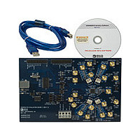
AD9959/PCB Analog Devices Inc, AD9959/PCB Datasheet - Page 13

AD9959/PCB
Manufacturer Part Number
AD9959/PCB
Description
Manufacturer
Analog Devices Inc
Datasheet
1.AD9959PCB.pdf
(28 pages)
Specifications of AD9959/PCB
Lead Free Status / RoHS Status
Not Compliant
Channel Output Config
The Channel Output Config window configures various output
characteristics of the channel(s). Use the Channel Select tabs to
select which specific channel options to configure. The following
describes the sections that are numerically indexed in Figure 23.
1. Single Tone Setup
Use the Single Tone Setup section to configure the channel
output for the single tone mode of operation (default).
Enter the desired output frequency directly in the Frequency 00
box or double-click the Frequency 00 box to launch the Edit
Output Frequency pop-up box to set the output frequency in
the Frequency box. The output frequency can alternatively be
set in decimal, hex, or binary format by editing the respective
boxes in the Tuning Word Values section (see Figure 24).
Note that the Phase Offset, Enable ASF, Amplitude Ramp
Rate, Profile Registers, Rising Step Size, Rising Step Interval,
Falling Step Size, and Falling Step Interval boxes all offer the
edit option shown in Figure 24 by double-clicking their
respective boxes.
1
2
3
Figure 24.
Figure 23. Channel Output Config Window
Rev. 0 | Page 13 of 28
The Frequency 00 box also sets the starting point of the linear
frequency sweep and the first level in frequency modulation (FSK).
Phase Offset consists of two boxes. In the first box, set the
integer factor (1–999) to increment or decrement the phase
offset by. The default setting of this box is 1, indicating that the
phase offset is incremented/decremented by .022 degrees when
pressing the up or down arrow keys. The value of .022 degrees is
derived from this equation:
Therefore, entering a factor of 3 in the first box will allow you to
increment/decrement the phase offset by .066 degrees. In the
second box, input the desired phase offset (from 0 degrees to
360 degrees) of the output signal.
The Phase Offset box also represents the starting point of the
linear phase sweep and the first level in phase modulation
(PSK).
In order to use the output amplitude scalar, the Enable ASF box
must be checked. In the first box, set the integer factor (1–999)
to increment or decrement the amplitude scale factor. The
default setting of this box is 1, meaning the output amplitude
will be scaled up/down by .00098 when pressing the up or down
arrow keys. The value of .00098 is derived from this equation:
In the second box, set the desired output amplitude scale factor
(between 0 and 1) of the output signal, where 1 is equivalent to
full scale.
IntegerFac
IntegerFac
tor
tor
×
×
(
(
2
2
(
(
14
10
bits
bits
of
of
output
phase
1
4
resolution
amplitude
1
scalar
)
AD9959/PCB
−
1
)
resolution
×
360
°
)
−
1
)


