BT168E,112 NXP Semiconductors, BT168E,112 Datasheet - Page 2
BT168E,112
Manufacturer Part Number
BT168E,112
Description
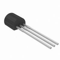
THYRISTOR .8A 500V TO-92
Manufacturer
NXP Semiconductors
Datasheet
1.BT168G112.pdf
(12 pages)
Specifications of BT168E,112
Package / Case
TO-92-3 (Standard Body), TO-226
Scr Type
Sensitive Gate
Voltage - Off State
500V
Voltage - Gate Trigger (vgt) (max)
800mV
Voltage - On State (vtm) (max)
1.7V
Current - On State (it (av)) (max)
500mA
Current - On State (it (rms)) (max)
800mA
Current - Gate Trigger (igt) (max)
200µA
Current - Hold (ih) (max)
5mA
Current - Off State (max)
100µA
Current - Non Rep. Surge 50, 60hz (itsm)
8A, 9A
Mounting Type
Through Hole
Current - On State (it (rms) (max)
800mA
Rated Repetitive Off-state Voltage Vdrm
500 V
Off-state Leakage Current @ Vdrm Idrm
0.05 mA
On-state Rms Current (it Rms)
0.8 A
Forward Voltage Drop
1.25 V
Gate Trigger Voltage (vgt)
0.3 V
Gate Trigger Current (igt)
50 uA
Holding Current (ih Max)
5 mA
Mounting Style
Through Hole
Lead Free Status / RoHS Status
Lead free / RoHS Compliant
Other names
568-3680
934042480112
BT168E
934042480112
BT168E


Philips Semiconductors
3. Ordering information
Table 2:
4. Limiting values
Table 3:
In accordance with the Absolute Maximum Rating System (IEC 60134).
[1]
9397 750 13511
Product data sheet
Type number
BT168E
BT168G
Symbol
V
I
I
I
I
dI
I
V
V
P
P
T
T
T(AV)
T(RMS)
TSM
2
GM
stg
j
DRM
t
GM
RGM
GM
G(AV)
T
/dt
Although not recommended, off-state voltages up to 800 V may be applied without damage, but the thyristor may switch to the on-state.
The rate of rise of current should not exceed 15 A/ s.
, V
RRM
Ordering information
Limiting values
Parameter
repetitive peak off-state voltage
average on-state current
RMS on-state current
non-repetitive peak on-state current
I
repetitive rate of rise of on-state
current after triggering
peak gate current
peak gate voltage
peak reverse gate voltage
peak gate power
average gate power
storage temperature
junction temperature
2
t for fusing
BT168E
BT168G
Package
Name
-
Description
plastic single-ended leaded (through hole) package; 3 leads
Rev. 04 — 20 August 2004
Conditions
half sine wave;
T
see
all conduction angles;
see
half sine wave;
T
surge;
see
t = 10 ms
I
dI
over any 20 ms period
TM
lead
j
G
t = 10 ms
t = 8.3 ms
= 25 C prior to
/dt = 100 mA/ s
= 2 A; I
Figure 1
Figure 4
Figure 2
Thyristors logic level for RCD/GFI/LCCB applications
83 C;
G
= 10 mA;
and
and
5
3
[1]
[1]
Min
-
-
-
-
-
-
-
-
-
-
-
-
-
-
40
© Koninklijke Philips Electronics N.V. 2004. All rights reserved.
BT168 series
Max
500
600
0.5
0.8
8
9
0.32
50
1
5
5
2
0.1
+150
125
Version
SOT54
Unit
V
V
A
A
A
A
A
A/ s
A
V
V
W
W
C
C
2
s
2 of 12
Related parts for BT168E,112
Image
Part Number
Description
Manufacturer
Datasheet
Request
R

Part Number:
Description:
SCRs BULK MOSFET
Manufacturer:
NXP Semiconductors
Datasheet:

Part Number:
Description:
NXP Semiconductors designed the LPC2420/2460 microcontroller around a 16-bit/32-bitARM7TDMI-S CPU core with real-time debug interfaces that include both JTAG andembedded trace
Manufacturer:
NXP Semiconductors
Datasheet:

Part Number:
Description:
NXP Semiconductors designed the LPC2458 microcontroller around a 16-bit/32-bitARM7TDMI-S CPU core with real-time debug interfaces that include both JTAG andembedded trace
Manufacturer:
NXP Semiconductors
Datasheet:
Part Number:
Description:
NXP Semiconductors designed the LPC2468 microcontroller around a 16-bit/32-bitARM7TDMI-S CPU core with real-time debug interfaces that include both JTAG andembedded trace
Manufacturer:
NXP Semiconductors
Datasheet:
Part Number:
Description:
NXP Semiconductors designed the LPC2470 microcontroller, powered by theARM7TDMI-S core, to be a highly integrated microcontroller for a wide range ofapplications that require advanced communications and high quality graphic displays
Manufacturer:
NXP Semiconductors
Datasheet:
Part Number:
Description:
NXP Semiconductors designed the LPC2478 microcontroller, powered by theARM7TDMI-S core, to be a highly integrated microcontroller for a wide range ofapplications that require advanced communications and high quality graphic displays
Manufacturer:
NXP Semiconductors
Datasheet:
Part Number:
Description:
The Philips Semiconductors XA (eXtended Architecture) family of 16-bit single-chip microcontrollers is powerful enough to easily handle the requirements of high performance embedded applications, yet inexpensive enough to compete in the market for hi
Manufacturer:
NXP Semiconductors
Datasheet:
Part Number:
Description:
The XA-S3 device is a member of Philips Semiconductors? XA(eXtended Architecture) family of high performance 16-bitsingle-chip microcontrollers
Manufacturer:
NXP Semiconductors
Datasheet:

Part Number:
Description:
The NXP BlueStreak LH75401/LH75411 family consists of two low-cost 16/32-bit System-on-Chip (SoC) devices
Manufacturer:
NXP Semiconductors
Datasheet:
Part Number:
Description:
The NXP LPC3130/3131 combine an 180 MHz ARM926EJ-S CPU core, high-speed USB2
Manufacturer:
NXP Semiconductors
Datasheet:
Part Number:
Description:
The NXP LPC3141 combine a 270 MHz ARM926EJ-S CPU core, High-speed USB 2
Manufacturer:
NXP Semiconductors
Part Number:
Description:
The NXP LPC3143 combine a 270 MHz ARM926EJ-S CPU core, High-speed USB 2
Manufacturer:
NXP Semiconductors

Part Number:
Description:
The NXP LPC3152 combines an 180 MHz ARM926EJ-S CPU core, High-speed USB 2
Manufacturer:
NXP Semiconductors
Part Number:
Description:
The NXP LPC3154 combines an 180 MHz ARM926EJ-S CPU core, High-speed USB 2
Manufacturer:
NXP Semiconductors