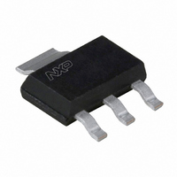
BLT70,115 NXP Semiconductors, BLT70,115 Datasheet

BLT70,115
Specifications of BLT70,115
BLT70 T/R
BLT70 T/R
Related parts for BLT70,115
BLT70,115 Summary of contents
Page 1
DISCRETE SEMICONDUCTORS DATA SHEET BLT70 UHF power transistor Product specification 1996 Feb 06 ...
Page 2
Philips Semiconductors UHF power transistor FEATURES Very high efficiency Low supply voltage. APPLICATIONS Hand-held radio equipment in common emitter class-AB operation in the 900 MHz communication band. DESCRIPTION NPN silicon planar epitaxial transistor encapsulated in a plastic SOT223H SMD package. ...
Page 3
Philips Semiconductors UHF power transistor LIMITING VALUES In accordance with the Absolute Maximum Rating System (IEC 134). SYMBOL PARAMETER V collector-base voltage CBO V collector-emitter voltage CEO V emitter-base voltage EBO I collector current (DC total power dissipation ...
Page 4
Philips Semiconductors UHF power transistor CHARACTERISTICS unless otherwise specified. j SYMBOL PARAMETER V collector-base breakdown voltage (BR)CBO V collector-emitter breakdown voltage (BR)CEO V emitter-base breakdown voltage (BR)EBO I collector leakage current CES h DC current gain ...
Page 5
Philips Semiconductors UHF power transistor APPLICATION INFORMATION RF performance common emitter test circuit (see note 1 and Fig.7). s MODE OF OPERATION CW, class-AB Note the temperature at the soldering point ...
Page 6
Philips Semiconductors UHF power transistor Test circuit information handbook, full pagewidth input typ. 4 bias Fig.7 Common emitter test circuit for class-AB operation at 900 MHz. 1996 ...
Page 7
Philips Semiconductors UHF power transistor List of components used in test circuit (see Figs 7 and 8) COMPONENT DESCRIPTION C1, C6, C9, C14 multilayer ceramic chip capacitor; note 1 C2 multilayer ceramic chip capacitor; note 1 C4 multilayer ceramic chip ...
Page 8
Philips Semiconductors UHF power transistor handbook, full pagewidth Copper foil Dimensions in mm. The components are situated on one side of the copper-clad PCB, the other side is unetched and serves as a ground plane. Earth ...
Page 9
Philips Semiconductors UHF power transistor 20 handbook, halfpage 800 850 900 0. ...
Page 10
Philips Semiconductors UHF power transistor PACKAGE OUTLINE handbook, full pagewidth o 16 max 1.80 max Dimensions in mm. 1996 Feb 06 S seating plane 0.32 6.7 0.24 6.3 3.1 2.9 0.10 0. 0.80 2.3 ...
Page 11
Philips Semiconductors UHF power transistor DEFINITIONS Data Sheet Status Objective specification This data sheet contains target or goal specifications for product development. Preliminary specification This data sheet contains preliminary data; supplementary data may be published later. Product specification This data ...


