ATF-541M4-BLK Avago Technologies US Inc., ATF-541M4-BLK Datasheet - Page 11
ATF-541M4-BLK
Manufacturer Part Number
ATF-541M4-BLK
Description
IC ENHANCED MOD SUDIOMORPHIC HEM
Manufacturer
Avago Technologies US Inc.
Datasheet
1.ATF-541M4-BLK.pdf
(16 pages)
Specifications of ATF-541M4-BLK
Gain
17.5dB
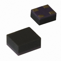
Package / Case
4-MiniPak (1412)
Current Rating
120mA
Power - Output
21.4dBm
Frequency
2GHz
Transistor Type
pHEMT FET
Noise Figure
0.5dB
Current - Test
60mA
Voltage - Test
3V
Drain Source Voltage Vds
3V
Continuous Drain Current Id
120mA
Power Dissipation Pd
360mW
Noise Figure Typ
0.5dB
Rf Transistor Case
MiniPak
No. Of Pins
4
Frequency Max
10GHz
Drain Current Idss Max
60mA
Rohs Compliant
Yes
Lead Free Status / RoHS Status
Lead free / RoHS Compliant
Other names
Q2380948


11
Electrostatic Sensitivity
FETs and RFICs are electrostatic dis‑
charge (ESD) sensitive devices. Avago
devices are manufactured using
a very robust and reliable PHEMT
process, however, permanent dam‑
age may occur to these devices if
they are subjected to high‑energy
electrostatic discharges. Electrostatic
charges as high as several thousand
volts (which readily accumulate on the
human body and on test equipment)
can discharge without detection and
may result in failure or degradation in
performance and reliability.
Figure 21. Leaded Solder Reflow Profile.
Figure 22. Lead-free Solder Reflow Profile.
350
300
250
221
200
150
100
250
200
150
100
50
50
0
0
0
0
30
60
Preheat 130 –170 C
60
Max. 150s
Min. 60s
90
Preheat
Zone
120
150
120
TIME (seconds)
TIME (seconds)
180
Electronic devices may be subjected
to ESD damage in any of the follow‑
ing areas:
• Storage & handling
• Inspection
• Assembly & testing
• In‑circuit use
The ATF‑541M4 is an ESD Class 1
device. Therefore, proper ESD pre‑
cautions are recommended when
handling, inspecting, testing, and
assembling these devices to avoid
damage.
Reflow
Zone
210
180
240
Cool Down
Zone
Peak Temperature
270
Max. 255 C
Min. 240 C
Reflow Time
Max. 90s
Min. 60s
240
300
T
MAX
330
360
300
Any user‑accessible points in wireless
equipment (e.g. antenna or battery
terminals) provide an opportunity for
ESD damage.
For circuit applications in which the
ATF‑541M4 is used as an input or
output stage with close coupling
to an external antenna, the device
should be protected from high volt‑
age spikes due to human contact with
the antenna. A good practice, illus‑
trated in Figure 23, is to place a shunt
inductor or RF choke at the antenna
connection to protect the receiver
and transmitter circuits. It is often ad‑
vantageous to integrate the RF choke
into the design of the diplexer or T/R
switch control circuitry.
Figure 23. In-circuit ESD Protection.
Related parts for ATF-541M4-BLK
Image
Part Number
Description
Manufacturer
Datasheet
Request
R

Part Number:
Description:
IC TRANS E-PHEMT 2GHZ SOT-343
Manufacturer:
Avago Technologies US Inc.
Datasheet:

Part Number:
Description:
IC PHEMT 2GHZ 3V 30MA SOT-343
Manufacturer:
Avago Technologies US Inc.
Datasheet:

Part Number:
Description:
IC PHEMT 2GHZ 2.7V 10MA MINIPAK
Manufacturer:
Avago Technologies US Inc.
Datasheet:

Part Number:
Description:
IC PHEMT 2GHZ 2.7V 10MA SOT-343
Manufacturer:
Avago Technologies US Inc.
Datasheet:
Part Number:
Description:
IC PHEMT 2GHZ 3V 60MA SOT-343
Manufacturer:
Avago Technologies US Inc.
Datasheet:
Part Number:
Description:
IC PHEMT 1.9GHZ 80MA LN SOT-343
Manufacturer:
Avago Technologies US Inc.
Datasheet:
Part Number:
Description:
IC PHEMT 1.9GHZ 15MA LN SOT-343
Manufacturer:
Avago Technologies US Inc.
Part Number:
Description:
IC PHEMT 1.9GHZ 15MA LN SOT-343
Manufacturer:
Avago Technologies US Inc.
Datasheet:
Part Number:
Description:
IC PHEMT 1.9GHZ 60MA LN SOT-343
Manufacturer:
Avago Technologies US Inc.
Datasheet:
Part Number:
Description:
IC TRANS E-PHEMT 2GHZ SOT-343
Manufacturer:
Avago Technologies US Inc.
Datasheet:
Part Number:
Description:
IC TRANS E-PHEMT 2GHZ SOT-343
Manufacturer:
Avago Technologies US Inc.
Datasheet:
Part Number:
Description:
IC TRANS E-PHEMT 2GHZ SOT-343
Manufacturer:
Avago Technologies US Inc.
Datasheet:

Part Number:
Description:
TRANSISTOR,HEMT,N-CHAN,5.5V V(BR)DSS,175mA I(DSS),SOT-343R
Manufacturer:
Avago Technologies US Inc.
Part Number:
Description:
TRANSISTOR,HEMT,N-CHAN,3V V(BR)DSS,15mA I(DSS),SOT-363
Manufacturer:
Avago Technologies US Inc.
Datasheet:
Part Number:
Description:
TRANSISTOR,HEMT,N-CHAN,4.5V V(BR)DSS,90mA I(DSS),SOT-343R
Manufacturer:
Avago Technologies US Inc.
Datasheet: