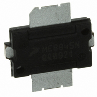
MRFE6S9045NR1 Freescale Semiconductor, MRFE6S9045NR1 Datasheet - Page 4

MRFE6S9045NR1
Manufacturer Part Number
MRFE6S9045NR1
Description
MOSFET RF N-CH 10W TO-270-2
Manufacturer
Freescale Semiconductor
Datasheet
1.MRFE6S9045NR1.pdf
(15 pages)
Specifications of MRFE6S9045NR1
Transistor Type
N-Channel
Frequency
880MHz
Gain
22.1dB
Voltage - Rated
66V
Current Rating
10µA
Current - Test
350mA
Voltage - Test
28V
Power - Output
10W
Package / Case
TO-270-2
Drain Source Voltage Vds
66V
Rf Transistor Case
TO-270
Termination Type
SMD
Output Power Pout
10W
Peak Reflow Compatible (260 C)
Yes
Transistor Polarity
N Channel
Rohs Compliant
Yes
Channel Type
N
Channel Mode
Enhancement
Drain Source Voltage (max)
66V
Output Power (max)
10W
Power Gain (typ)@vds
22.1/20/20dB
Frequency (max)
1GHz
Package Type
TO-270
Pin Count
3
Input Capacitance (typ)@vds
81@28VpF
Output Capacitance (typ)@vds
27@28VpF
Reverse Capacitance (typ)
1.02@28VpF
Operating Temp Range
-65C to 225C
Drain Efficiency (typ)
32%
Mounting
Surface Mount
Mode Of Operation
1-Carrier N-CDMA/CW/GSM EDGE
Number Of Elements
1
Vswr (max)
5
Screening Level
Military
Filter Terminals
SMD
Gate-source Voltage
12V
Leaded Process Compatible
Yes
Operating Frequency Max
880MHz
Lead Free Status / RoHS Status
Contains lead / RoHS Compliant
Noise Figure
-
Lead Free Status / Rohs Status
Compliant
Other names
MRFE6S9045NR1
MRFE6S9045NR1TR
MRFE6S9045NR1TR
Available stocks
Company
Part Number
Manufacturer
Quantity
Price
Company:
Part Number:
MRFE6S9045NR1
Manufacturer:
ELNA
Quantity:
4 000
Part Number:
MRFE6S9045NR1
Manufacturer:
FREESCALE
Quantity:
20 000
MRFE6S9045NR1
4
Table 6. MRFE6S9045NR1 Test Circuit Component Designations and Values
INPUT
B1
B2
C1, C7, C10, C14
C2, C4, C12
C3
C5, C6
C8, C9
C11
C13
C15, C16, C17
C18
L1, L2
R1
R2
R3
RF
V
BIAS
Z1
C1
Part
Z1
Z2
Z3
Z4
Z5
Z6
Z7
Z8
Z9
C15
Z2
+
R1
Z3
R2
Z4
0.215″ x 0.065″ Microstrip
0.221″ x 0.065″ Microstrip
0.500″ x 0.100″ Microstrip
0.460″ x 0.270″ Microstrip
0.040″ x 0.270″ Microstrip
0.280″ x 0.270″ x 0.530″ Taper
0.087″ x 0.525″ Microstrip
0.435″ x 0.525″ Microstrip
0.057″ x 0.525″ Microstrip
B1
R3
C2
Ferrite Bead
Ferrite Bead
47 pF Chip Capacitors
0.8 - 8.0 pF Variable Capacitors, Gigatrim
15 pF Chip Capacitor
12 pF Chip Capacitors
13 pF Chip Capacitors
7.5 pF Chip Capacitor
0.6 - 4.5 pF Variable Capacitor, Gigatrim
10 μF, 35 V Tantalum Capacitors
220 μF, 50 V Electrolytic Capacitor
12.5 nH Inductors
1 kΩ, 1/4 W Chip Resistor
560 kΩ, 1/4 W Chip Resistor
12 Ω, 1/4 W Chip Resistor
Z5
Figure 1. MRFE6S9045NR1 Test Circuit Schematic
Z6
C7
C3
L1
Z7
Description
C4
Z8
C5
C6
Z9
Z10
Z11
Z12
Z13
Z14
Z15
Z16
PCB
DUT
Z10
2743019447
2743021447
ATC100B470JT500XT
27291SL
ATC100B150JT500XT
ATC100B120JT500XT
ATC100B130JT500XT
ATC100B7R5JT500XT
27271SL
T491D106K035AT
EMVY500ADA221MJA0G
A04T - 5
CRCW12061001FKEA
CRCW120656001FKEA
CRCW120612R0FKEA
0.360″ x 0.270″ Microstrip
0.063″ x 0.270″ Microstrip
0.360″ x 0.065″ Microstrip
0.095″ x 0.065″ Microstrip
0.800″ x 0.065″ Microstrip
0.260″ x 0.065″ Microstrip
0.325″ x 0.065″ Microstrip
Taconic RF - 35 0.030″, ε
C8
C9
Z11
Part Number
L2
Z12
C10
B2
C11
Z13
C16
+
C12
r
Freescale Semiconductor
Z14
= 3.5
C17
+
Fair Rite
Fair Rite
ATC
Johanson
ATC
ATC
ATC
ATC
Johanson
Kemet
Nippon Chemi - con
Coilcraft
Vishay
Vishay
Vishay
Z15
C13
Manufacturer
C18
+
C14
RF Device Data
V
SUPPLY
Z16
OUTPUT
RF


