AC8A OPTO 22, AC8A Datasheet - Page 4
AC8A
Manufacturer Part Number
AC8A
Description
Computers, Interface Cards
Manufacturer
OPTO 22
Datasheet
1.AC8.pdf
(11 pages)
Specifications of AC8A
Peak Reflow Compatible (260 C)
No
Leaded Process Compatible
No
Features
Half Duplex Modem Interface, 115VAC
Lead Free Status / RoHS Status
Lead free / RoHS Compliant


DATA SHEET
Form 043-061030
Opto 22 • 43044 Business Park Drive • Temecula, CA 92590-3614 • Phone: (951) 695-3000 • (800) 321-OPTO • Fax: (951) 695-3095 • www.opto22.com
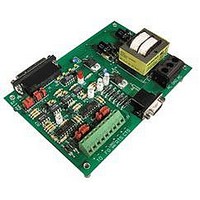
LED Indicators
PWR ON, FO, and TO LEDs. The PWR ON is on when power is applied to the AC8 adapter card. The FO (From Optomux) and TO (To
Optomux) LEDs refer to the RS-422/485 receive and transmit data signals, respectively.
Configuration Jumpers
of the AC8. The five jumper groups are: delay, baud rate, data flow control, pins 2 & 3 in/out and communication.
There are nine LEDs on the AC8, which indicate power, control and data signals
The following table lists the LEDs and their descriptions. The LEDs indicate the state of the RS-232 signals with the exception of the
There are five groups of configuration jumpers on the AC8 card. The configuration jumpers allow the user to configure the operation
Inside Sales: (800) 321-OPTO • Product Support: (800) TEK-OPTO • (951) 695-3080 • Fax: (951) 695-3017 • Email: sales@opto22.com
PWR ON Power On
© 2004 Opto 22. All rights reserved. All trademarks, trade names, logos, and service marks referenced herein belong to their respective companies.
LED
TXD
RXD
FO
TO
Received Data
From Optomux
Transmit Data
To Optomux
Description
DCD
LED
DSR
CTS
RTS
Figure 2 - Layout of the AC8 LED’s
Data Carrier Detect
Data Set Ready
Clear To Send
Request to Send
TRADITIONAL ADAPTER CARDS
Description
INTERFACES
STAND-ALONE
page 4/11
Related parts for AC8A
Image
Part Number
Description
Manufacturer
Datasheet
Request
R

Part Number:
Description:
Computers, Interface Cards
Manufacturer:
OPTO 22
Datasheet:

Part Number:
Description:
SSR, PANEL MOUNT, 280VAC, 32VDC, 10A
Manufacturer:
OPTO 22
Datasheet:

Part Number:
Description:
SSR, PANEL MOUNT, 280VAC, 32VDC, 25A
Manufacturer:
OPTO 22
Datasheet:
Part Number:
Description:
SSR, PANEL MOUNT, 280VAC, 32VDC, 25A
Manufacturer:
OPTO 22
Datasheet:
Part Number:
Description:
SSR, PANEL MOUNT, 280VAC, 32VDC, 45A
Manufacturer:
OPTO 22
Datasheet:
Part Number:
Description:
SSR, PANEL MOUNT, 280VAC, 32VDC, 45A
Manufacturer:
OPTO 22
Datasheet:

Part Number:
Description:
SSR, 10A, 240VAC
Manufacturer:
OPTO 22
Datasheet:

Part Number:
Description:
Programmable Logic Controller
Manufacturer:
OPTO 22
Datasheet:

Part Number:
Description:
Programmable Logic Controller
Manufacturer:
OPTO 22
Datasheet:

Part Number:
Description:
Solid State Relays, Accessories
Manufacturer:
OPTO 22
Datasheet:
