E2 OPTO 22, E2 Datasheet
E2
Specifications of E2


Related parts for E2


E2 Summary of contents
Page 1
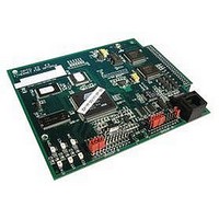
... I/O systems. The E1 connects to a rack of Opto 22 G1, G4, or Quad Pak modules, while the E2 connects to a rack of Opto 22 G1 analog I/O modules. Each brain board communicates with a host computer and performs control functions for each I/O point. ...
Page 2
... Ethernet network, I/O point, and other E1 and E2 configuration settings are made using Opto 22's PAC Manager configuration software. This software is included on the CD shipped with E1s and E2s, and is also available as a free download from the Opto 22 website. Optomux Compatibility E1 and E2 brain boards are designed as drop-in replacements for Opto 22 B1 and B2 brain boards ...
Page 3
... E1 and E2 Brain Boards Optomux Protocol Brain Comparison The following table compares Opto 22’s Optomux-capable brain boards: B1, E1, B2, and E2. Features shown are for the Feature Optomux Digital Features Read/write to point Input latching Counting Pulse duration measurement Pulse generation Time delays (10 ms resolution) ...
Page 4
... One latch per point is available; it can be configured as on-to-off or off-to-on. 3 Two latches per point are always available; no configuration is needed. 4 Maximum counter frequency is 400 Hz. Counters roll over at 65,535. E2 Features and Protocols The following table shows features available I/O analog unit depending on the protocol used. Feature Read/write to point in Engineering units ...
Page 5
... Optomux applications for serial networks can be converted to use Ethernet networks. The Optomux Protocol Driver and documentation are included with E1 and E2 brain boards, and can also be downloaded free of charge from the Opto 22 website. For more information on using E1 and E2 brain boards, see the E1 and E2 User’ ...
Page 6
... Optomux-based I/O system for an RS-422/485 serial network can be migrated to an Ethernet network. In this system, each original brain board has been replaced with E2, and all brain boards are connected to an Ethernet network. One brain board is connected via an RS-422/485 serial connection to the host PC running the Optomux application ...
Page 7
... E1 and E2 Brain Boards Integrating E1- or E2-based I/O into a PAC Project™-based System PC used to develop PAC Control strategy E2 PC running PAC Display HMI for operator SNAP PAC Ethernet brain with SNAP digital modules OptoOPCServer providing SNAP PAC Ethernet brain with analog, HDD*, and serial modules OPC data to any OPC client ™ ...
Page 8
... This diagram shows an E1- and E2- based I/O system controlled by Modbus/TCP software. In this system, each original brain board has been replaced with E2, and all brain boards are connected to an Ethernet network. Modbus/TCP software running communicates with the E1s and E2s over the Ethernet network to control and monitor I/O points ...
Page 9
... Digital I/O (E1): Read Point, Write Point, Latch Point (On/Off), Count, Pulse Duration, Time Delay, Pulse Generation, Watchdog Timer Optomux I/O Functions Analog I/O (E2): Read Point, Write Point, Input Averaging, Min/Max Recording (peak and valley), High/Low Range Testing, Offset and Gain Calculation, Waveform Generation, Watchdog Timer ...
Page 10
... SALES 800-321-6786 • 951-695-3000 • FAX 951-695-3095 • sales@opto22.com • SUPPORT 800-835-6786 • 951-695-3080 • FAX 951-695-3017 • support@opto22.com © 2011 Opto 22. All rights reserved. Dimensions and specifications are subject to change. Brand or product names used herein are trademarks or registered trademarks of their respective companies or organizations. ...