AC8 OPTO 22, AC8 Datasheet
AC8
Specifications of AC8
Available stocks


Related parts for AC8


AC8 Summary of contents
Page 1
... Optomux network. The AC8 provides transient protection on the RS-422/485 port. The modem adapter card operates as a half or full duplex device with transmission speeds up to 9,600 baud for distances up to 5,000 feet using two twisted pairs. ...
Page 2
... DATA SHEET Form 043-061030 Features The AC8 includes the following features: • Baud rates of 300, 1200, 2400, 4800, and 9600 baud. • LEDs to indicate the state of all modem control and data signals. • Signal delay from Clear to Send (CTS) to beginning of data transmission adjustable to 1, 25, 100, or 500 milliseconds. ...
Page 3
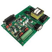
... C. The relative humidity is from non-condensing. Physical Description The AC8 is a rectangular, printed circuit board designed to bolt to a panel inside an electrical enclosure. The layout of the AC8 is the same for both versions of the AC8 adapter card. Figure 1 - Dimensions and Layout of the AC8 Adapter Card Opto 22 • ...
Page 4
... The following table lists the LEDs and their descriptions. The LEDs indicate the state of the RS-232 signals with the exception of the PWR ON, FO, and TO LEDs. The PWR when power is applied to the AC8 adapter card. The FO (From Optomux) and TO (To Optomux) LEDs refer to the RS-422/485 receive and transmit data signals, respectively. ...
Page 5
... Baud Rate The baud rate jumper (Figure 3) determines the baud rate of the AC8. Selectable baud rates are: 300, 600, 1200, 2400, 4800, and 9600. The AC8 must be set to the same baud rate as the modem and the Optomux network. The default baud rate is 1200 baud. ...
Page 6
... Form 043-061030 Pin 2 & 3 In/Out The pin 2 & 3 In/Out jumpers (Figure 4) allow the AC8 to be used with either a null modem (pin and pin straight-through (pin and pin cable. The default jumper setting is for the straight-through cable, jumpers on PIN 3 OUT and PIN 2 IN. To configure for a null modem cable, install jumpers on PIN 3 IN and PIN 2 OUT. ...
Page 7
... Figure 5 - Jumpers for the Optomux Communication Opto 22 • 43044 Business Park Drive • Temecula, CA 92590-3614 • Phone: (951) 695-3000 • (800) 321-OPTO • Fax: (951) 695-3095 • www.opto22.com Inside Sales: (800) 321-OPTO • Product Support: (800) TEK-OPTO • (951) 695-3080 • Fax: (951) 695-3017 • Email: sales@opto22.com © ...
Page 8
... The AC8/AC8A/AC8B (Figure 6), is designed to operate inside an electrical enclosure. Mount the AC8 to a surface with screws through the four stand-offs in the corners of the AC8 adapter card. The AC8 can be mounted in any physical orientation. Figure 6 - Dimensions and Layout of the AC8 Adapter Card Opto 22 • ...
Page 9
... Connecting a Modem to the AC8 To connect a modem to the AC8, follow the steps below: 1. Connect the DB25 RS-232 cable to your modem. 2. The other end which will connect to the AC8, must be a male DB25 connector. The pinout of the AC8 connector is described below. Pin Description ...
Page 10
... DSR or DCD is not provided by the modem, you can jumper those signals to be permanently true on the AC8. Transmitting From Optomux To Host When an Optomux brain board sends a reply on the Optomux network, the AC8 stores the message in its buffer. It sets a true condition on the control line. ...
Page 11
... Opto 22 • 43044 Business Park Drive • Temecula, CA 92590-3614 • Phone: (951) 695-3000 • (800) 321-OPTO • Fax: (951) 695-3095 • www.opto22.com Inside Sales: (800) 321-OPTO • Product Support: (800) TEK-OPTO • (951) 695-3080 • Fax: (951) 695-3017 • Email: sales@opto22.com • Form 1335-050601 © ...