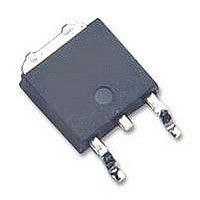
IGB03N120H2 Infineon Technologies, IGB03N120H2 Datasheet - Page 8

IGB03N120H2
Manufacturer Part Number
IGB03N120H2
Description
IGBT 1200V 9.6A 62.5W TO263-3
Manufacturer
Infineon Technologies
Datasheet
1.IGB03N120H2.pdf
(12 pages)
Specifications of IGB03N120H2
Voltage - Collector Emitter Breakdown (max)
1200V
Vce(on) (max) @ Vge, Ic
2.8V @ 15V, 3A
Current - Collector (ic) (max)
9.6A
Power - Max
62.5W
Input Type
Standard
Mounting Type
Surface Mount
Package / Case
SC-70-6, SC-88, SOT-363
Dc Collector Current
3A
Collector Emitter Voltage Vces
2.8V
Power Dissipation Max
62.5W
Collector Emitter Voltage V(br)ceo
1.2kV
Operating Temperature Range
-40°C To +150°C
Transistor Case Style
TO-263
No.
RoHS Compliant
No. Of Pins
3
Rohs Compliant
Yes
Switching Frequency
HighSpeed2 30-100 kHz
Package
D2PAK (TO-263)
Vce (max)
1,200.0 V
Ic(max) @ 25°
9.6 A
Ic(max) @ 100°
3.9 A
Lead Free Status / RoHS Status
Lead free / RoHS Compliant
Igbt Type
-
Lead Free Status / RoHS Status
Lead free / RoHS Compliant
Available stocks
Company
Part Number
Manufacturer
Quantity
Price
Company:
Part Number:
IGB03N120H2
Manufacturer:
INFINEON
Quantity:
12 500
Power Semiconductors
10
10
100pF
10
10pF
Figure 17. Typical gate charge
(I
Figure 18. Typical capacitance as a
function of collector-emitter voltage
(V
-1
-2
0
1nF
K/W
K/W
K/W
C
GE
V
= 3A)
1µs
0V
CE
0.02
0.05
= 0V, f = 1MHz)
0.1
0.01
D=0.5
0.2
,
COLLECTOR
single pulse
10µs
Q
GE
10V
,
1.082517
0.328671
0.588811
GATE CHARGE
R , ( K / W )
100µs
R
1
C
-
EMITTER VOLTAGE
1
=
1
/ R
1ms
20V
1
0.000795
0.000179
0.004631
C
2
, ( s )
=
10ms
2
/R
R
2
30V
2
100ms
C
C
C
oss
rss
iss
8
1000V
20V
15V
10V
800V
600V
400V
200V
Figure 17. Typical gate charge
(I
Figure 20. Typical turn off behavior, hard
switching
(V
Dynamic test circuit in Figure E)
5V
0V
0V
C
0nC
GE
= 3A)
=15/0V, R
0.0
0.2
Q
U
t
GE
CE
p
10nC
0.4
,
G
=240V
,
PULSE WIDTH
=82Ω, T
GATE CHARGE
0.6
IGB03N120H2
0.8
j
= 150 C,
20nC
U
1.0
CE
=960V
Rev. 2.4 Oct. 07
1.2
3A
2A
1A
0A
30nC


