STGF14NC60KD STMicroelectronics, STGF14NC60KD Datasheet - Page 3
STGF14NC60KD
Manufacturer Part Number
STGF14NC60KD
Description
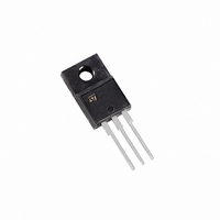
IGBT N-CH 600V 11A TO-220FP
Manufacturer
STMicroelectronics
Series
PowerMESH™r
Datasheet
1.STGF14NC60KD.pdf
(16 pages)
Specifications of STGF14NC60KD
Voltage - Collector Emitter Breakdown (max)
600V
Vce(on) (max) @ Vge, Ic
2.5V @ 15V, 7A
Current - Collector (ic) (max)
11A
Power - Max
28W
Input Type
Standard
Mounting Type
Through Hole
Package / Case
TO-220-3 Full Pack (Straight Leads)
Transistor Type
IGBT
Dc Collector Current
11A
Collector Emitter Voltage Vces
2.5V
Power Dissipation Pd
28W
Collector Emitter Voltage V(br)ceo
600V
Operating Temperature Range
-55°C To +150°C
Rohs Compliant
Yes
Lead Free Status / RoHS Status
Lead free / RoHS Compliant
Igbt Type
-
Lead Free Status / Rohs Status
Compliant
Other names
497-5115-5
Available stocks
Company
Part Number
Manufacturer
Quantity
Price
Company:

Part Number:
STGF14NC60KD
Manufacturer:
STMicroelectronics
Quantity:
1 827
Company:
Part Number:
STGF14NC60KD
Manufacturer:
INFINEON
Quantity:
10 000
Part Number:
STGF14NC60KD
Manufacturer:
ST
Quantity:
20 000


STGB14NC60KD, STGF14NC60KD, STGP14NC60KD
1
Electrical ratings
Table 2.
1.
2. Vclamp = 80% of V
3. Pulse width limited by maximum junction temperature and turn-off within RBSOA
Table 3.
Symbol
Symbol
R
R
R
I
I
V
P
CL
CP
I
V
thj-case
thj-case
I
I
V
thj-amb
t
FSM
C
C
scw
Calculated according to the iterative formula
CES
TOT
T
I
ISO
GE
F
(1)
(1)
j
(2)
(3)
Collector-emitter voltage (V
Continuous collector current at T
Continuous collector current at T
Turn-off latching current
Pulsed collector current
Gate-emitter voltage
Diode RMS forward current at T
Surge non repetitive forward current t
sinusoidal
Insulation withstand voltage (RMS) from all three
leads to external hea sink
( t=1 s; T
Total dissipation at T
Short circuit withstand time, V
T
Operating junction temperature
Thermal resistance junction-case IGBT
Thermal resistance junction-case diode
Thermal resistance junction-ambient
C
Absolute maximum ratings
Thermal data
= 125 °C, R
C
CES
= 25 °C)
, T
I
C
G
j
(
=150 °C, R
T
= 10 Ω, V
C
)
Parameter
C
=
Parameter
Doc ID 11424 Rev 7
= 25 °C
--------------------------------------------------------------------------------------------------------- -
R
thj c
G
GE
=10 Ω, V
GE
–
CE
= 12 V
= 0)
×
C
C
C
= 0.5V
V
= 25 °C
= 25 °C
= 100 °C
CE sat
GE
=15 V
p
(
T
= 10 ms
j max
BR(CES)
(
) max
(
)
–
)
(
T
T
,
C
j max
(
TO-220/D²PAK TO-220FP
)
,
TO-220/D²PAK TO-220FP
I
C
(
T
25
14
80
--
C
1.56
2.2
– 55 to 150
)
)
Value
±20
600
Value
50
20
50
55
10
62.5
Electrical ratings
2500
11
28
7
4.5
5.6
Unit
°C/W
°C/W
°C/W
Unit
°C
µs
W
V
A
A
A
A
V
A
A
V
3/16
Related parts for STGF14NC60KD
Image
Part Number
Description
Manufacturer
Datasheet
Request
R

Part Number:
Description:
STMicroelectronics [RIPPLE-CARRY BINARY COUNTER/DIVIDERS]
Manufacturer:
STMicroelectronics
Datasheet:
Part Number:
Description:
STMicroelectronics [LIQUID-CRYSTAL DISPLAY DRIVERS]
Manufacturer:
STMicroelectronics
Datasheet:

Part Number:
Description:
BOARD EVAL FOR MEMS SENSORS
Manufacturer:
STMicroelectronics
Datasheet:
Part Number:
Description:
NPN TRANSISTOR POWER MODULE
Manufacturer:
STMicroelectronics
Datasheet:
Part Number:
Description:
TURBOSWITCH ULTRA-FAST HIGH VOLTAGE DIODE
Manufacturer:
STMicroelectronics
Datasheet:
Part Number:
Description:
Manufacturer:
STMicroelectronics
Datasheet:
Part Number:
Description:
DIODE / SCR MODULE
Manufacturer:
STMicroelectronics
Datasheet:
Part Number:
Description:
DIODE / SCR MODULE
Manufacturer:
STMicroelectronics
Datasheet:
Part Number:
Description:
Search -----> STE16N100
Manufacturer:
STMicroelectronics
Datasheet:
Part Number:
Description:
Search ---> STE53NA50
Manufacturer:
STMicroelectronics
Datasheet:
Part Number:
Description:
NPN Transistor Power Module
Manufacturer:
STMicroelectronics
Datasheet:
Part Number:
Description:
DIODE / SCR MODULE
Manufacturer:
STMicroelectronics
Datasheet: