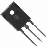
APT27GA90BD15 Microsemi Power Products Group, APT27GA90BD15 Datasheet

APT27GA90BD15
Specifications of APT27GA90BD15
APT27GA90BD15MI
Related parts for APT27GA90BD15
APT27GA90BD15 Summary of contents
Page 1
... 1.0mA 15V 14A 1mA 900V ±30V GS Microsemi Website - http://www.microsemi.com APT27GA90BD15 is achieved off - off APT27GA90BD15 Combi (IGBT and Diode) Ratings 900 ±30 223 79A @ 900V -55 to 150 300 Min Typ Max 900 T = 25°C 2.5 3 125° 25°C 350 ...
Page 2
... GE L= 100uH 900V CE Inductive Switching (25° 600V 15V 14A 10Ω +25°C J Inductive Switching (125° 600V 15V 14A 10Ω +125°C J APT27GA90BD15 Min Typ Max Unit 1390 145 413 μJ 287 137 144 760 μJ 647 Min Typ Max Unit - - .56 °C/W 1 ...
Page 3
... JUNCTION TEMPERATURE J FIGURE 7, Threshold Voltage vs Junction Temperature T = 150° 25° -55° 25°C. J 250μs PULSE TEST <0.5 % DUTY CYCLE I = 28A 100 125 150 APT27GA90BD15 250 15V 225 13V 200 175 11V 150 10V 125 9V 100 COLLECTOR-TO-EMITTER VOLTAGE (V) CE FIGURE 2, Output Characteristics (T = 25° ...
Page 4
... T 25°C J 200 FIGURE 14, Turn-Off Energy Loss vs Collector Current 2000 1500 28A off, 1000 500 E 7A on2 off FIGURE 16, Switching Energy Losses vs Junction Temperature APT27GA90BD15 V =15V,T =125° =15V,T =25° 600V 10Ω 100μ COLLECTOR-TO-EMITTER CURRENT (A) CE ...
Page 5
... FIGURE 19b, TRANSIENT THERMAL IMPEDANCE MODEL C ies C oes C res 600 800 SINGLE PULSE - RECTANGULAR PULSE DURATION (SECONDS) T (°C) C .31601 .14513 APT27GA90BD15 1000 100 100 V , COLLECTOR-TO-EMITTER VOLTAGE CE FIGURE 18, Minimum Switching Safe Operating Area Note Duty Factor Peak θ 0.1 ...
Page 6
... J 90% t d(off Switching Energy Figure 22, Turn-off Switching Waveforms and Defi nitions Gate Voltage Switching Energy Figure 21, Turn-on Switching Waveforms and Defi nitions Gate Voltage Collector Voltage Collector Current APT27GA90BD15 10 125°C J 90% t d(on) Collector Current Collector Voltage ...
Page 7
... 667V 125° SINGLE PULSE - RECTANGULAR PULSE DURATION (seconds) T (°C) T (° 0.676 0.504 0.00147 0.0440 FIGURE 1b, TRANSIENT THERMAL IMPEDANCE MODEL = 25°C unless otherwise specifi ed. C APT27GA90BD15 Min Type Max 2.5 3.06 1.92 Min Typ Max 235 - - - 185 - - 3 - 300 ...
Page 8
... Figure 3. Reverse Recovery Time vs. Current Rate of Change 15A 800 1000 1200 Figure 5. Reverse Recovery Current vs. Current Rate of Change 100 125 150 Figure 7. Maximum Average Forward Current vs. CaseTemperature 100 200 APT27GA90BD15 400 T = 125°C 30A 667V R 350 300 15A 250 200 7.5A ...
Page 9
... BSC 20.80 (.819) 21.46 (.845) 4.50 (.177) Max. 19.81 (.780) 20.32 (.800) 1.01 (.040) 1.40 (.055) 5.45 (.215) BSC 2-Plcs. Dimensions in Millimeters and (Inches) APT27GA90BD15 APT10035LLL D.U. Waveform PEARSON 2878 CURRENT TRANSFORMER 15.49 (.610) 16 ...


