BAS 16 B5003 Infineon Technologies, BAS 16 B5003 Datasheet
BAS 16 B5003
Specifications of BAS 16 B5003
BAS16B5003XT
SP000223866


Related parts for BAS 16 B5003


BAS 16 B5003 Summary of contents
Page 1
Silicon Switching Diode • For high-speed switching applications • Pb-free (RoHS compliant) package • Qualified according AEC Q101 BAS16 BAS16-02L BAS16W BAS16-02V BAS16-02W BAS16-03W Type BAS16 BAS16-02L* BAS16-02V BAS16-02W BAS16-03W BAS16-07L4* BAS16S BAS16U BAS16W * Preliminary Data 1 Pb-containing package ...
Page 2
Maximum Ratings °C, unless otherwise specified A Parameter Diode reverse voltage Peak reverse voltage Forward current BAS16 BAS16-02L, -07L4 BAS16-02V, -02W BAS16-03W BAS16S BAS16U BAS16W Non-repetitive peak surge forward current µs, BAS16/ S/ ...
Page 3
Thermal Resistance Parameter 1) Junction - soldering point BAS16, BAS16S BAS16-02L, -07L4 BAS16-02V, -02W BAS16-03W BAS16U BAS16W Electrical Characteristics at T Parameter DC Characteristics Breakdown voltage I = 100 µA (BR) Reverse current ...
Page 4
Electrical Characteristics at T Parameter AC Characteristics Diode capacitance MHz R Reverse recovery time mA mA, measured 100 Ω Test ...
Page 5
Reverse current Parameter ƒ (V Forward current 25°C A BAS ...
Page 6
Forward current BAS16-02L, -07L4 250 mA 150 100 ƒ (T Forward current BAS16-03W 300 mA 200 150 100 ...
Page 7
Forward current BAS16U 250 mA 200 175 150 125 100 Permissible Puls Load R thJS BAS16 ...
Page 8
Permissible Puls Load R thJS BAS16-02L, -07L4 2 10 K/W 0.5 1 0.2 10 0.1 0.05 0.02 0.01 0.005 Permissible Puls Load R thJS BAS16-02V, -02W ...
Page 9
Permissible Puls Load R thJS BAS16-03W D=0.5 0.2 1 0.1 10 0.05 0.02 0.01 0.005 Permissible Puls Load R thJS BAS16S 3 10 K/W ...
Page 10
Permissible Puls Load R thJS BAS16U D=0.5 0.2 1 0.1 10 0.05 0.02 0.01 0.005 Permissible Puls Load R thJS BAS16W 3 10 K/W ...
Page 11
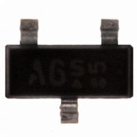
Package Outline 2.9 (2.25 Pin 1 marking Foot Print Marking Layout (Example) Small variations in positioning of Date code, Type code and Manufacture are possible. Pin 1 marking Laser marking Standard Packing Reel ø180 mm = 3.000 Pieces/Reel ...
Page 12
Package Outline Foot Print Marking Layout (Example) Standard Packing Reel ø180 mm = 3.000 Pieces/Reel Reel ø180 mm = 8.000 Pieces/Reel (2 mm Pitch) Reel ø330 mm = 10.000 Pieces/Reel Standard 4 0.4 Cathode marking 0.93 Package SC79 0.2 M ...
Page 13
Package Outline Cathode marking Foot Print Marking Layout (Example) Standard Packing Reel ø180 mm = 3.000 Pieces/Reel Reel ø180 mm = 8.000 Pieces/Reel (2 mm Pitch) Reel ø330 mm = 10.000 Pieces/Reel Standard 4 Cathode marking Package SCD80 0.2 A ...
Page 14
Date Code marking for discrete packages with one digit (SCD80, SC79, SC75 Month ...
Page 15
Package SOD323 15 BAS16... 2009-09-28 ...
Page 16
Package Outline Foot Print Marking Layout (Example) Standard Packing Reel ø180 mm = 3.000 Pieces/Reel Reel ø330 mm = 10.000 Pieces/Reel Pin 1 Package SOT23 2.9 ±0 +0.1 0.4 -0.05 C 0.95 1.9 0.25 B ...
Page 17
Package Outline Foot Print Marking Layout (Example) Standard Packing Reel ø180 mm = 3.000 Pieces/Reel Reel ø330 mm = 10.000 Pieces/Reel Package SOT323 2 ±0.2 0.1 MAX. +0.1 3x 0.3 -0.05 0 0.65 0.65 0.2 0.6 ...
Page 18
Package Outline Pin 1 marking Foot Print Marking Layout (Example) Small variations in positioning of Date code, Type code and Manufacture are possible. Pin 1 marking Laser marking Standard Packing Reel ø180 mm = 3.000 Pieces/Reel Reel ø330 mm = ...
Page 19
Package Outline Top view 2 1 Cathode marking 1) Dimension applies to plated terminal Foot Print For board assembly information please refer to Infineon website "Packages" Copper Marking Layout (Example) Standard Packing Reel ø180 mm = 15.000 Pieces/Reel Reel ø330 ...
Page 20
Package TSLP-4-4 20 BAS16... 2009-09-28 ...
Page 21
... For information on the types in question please contact your nearest Infineon Technologies Office. Infineon Technologies Components may only be used in life-support devices or systems with the express written approval of Infineon Technologies failure of such components can reasonably be expected to cause the failure of that life-support device or system affect the safety or effectiveness of that device or system ...