P7S-14F Omron, P7S-14F Datasheet - Page 14
P7S-14F
Manufacturer Part Number
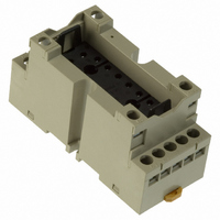
P7S-14F
Description
Contact OSTI
Manufacturer
Omron
Series
G7Sr
Type
Socketr
Specifications of P7S-14F
Number Of Positions
14
Mounting Type
DIN Rail
Termination Style
Screw Terminal
Socket Mounting
DIN Rail
Socket Terminals
Screw
Voltage Rating
24VDC
Rohs Compliant
Yes
Lead Free Status / RoHS Status
Lead free / RoHS Compliant
For Use With/related Products
G7S Series
For Use With
Z2362 - RELAY SAFETY 6A 24VDC PLUG-INZ2363 - RELAY SAFETY 6A 24VDC PLUG-IN
Lead Free Status / RoHS Status
Lead free / RoHS Compliant
Other names
P7S14F
Z2417
Z2417
Available stocks
Company
Part Number
Manufacturer
Quantity
Price
Company:

Part Number:
P7S-14F
Manufacturer:
Omron Electronics Inc-EMC Div
Quantity:
135


C-B-11 Using DC-operated Relays
For a DC-operated Relay power supply, use a power supply with a
maximum ripple percentage of 5%. An increase in the ripple
percentage will cause humming.
C-B-12 Using DC-operated Relays
To make the correct connections, first check the individual terminal
numbers and applied power supply polarities provided in this catalog.
If the polarity is connected in reverse for the coil power supply when
Relays with surge suppressor diodes or Relays with operation
indicators are used, it can cause problems such as Relay
malfunctioning, damage to diodes, or failure of indicators. Also, for
Relays with diodes, it can cause damage to devices in the circuit due
to short-circuiting.
Polarized Relays that use a permanent magnet in a magnetic circuit
will not operate if the power supply to the coil is connected in reverse.
C-B-13 Using DC-operated Relays
If insufficient voltage is applied to the coil, either the Relay will not
operate or operation will be unstable. This will cause problems such
as a drop in the electrical durability of the contacts and contact
welding.
In particular, when a load with a large surge current, such as a large
motor, is used, the voltage applied to the coil may drop when a large
inrush current occurs to operate the load as the power is turned ON.
Also, if a Relay is operated while the voltage is insufficient, it will
cause the Relay to malfunction even at vibration and shock values
below the specifications specified in the specification sheets and this
catalog. Therefore, be sure to apply the rated voltage to the coil.
C Mounting Design
C-C-1 Lead Wire Diameters
Lead wire diameters are determined by the size of the load current.
As a standard, use lead wires at least the size of the cross-sectional
areas shown in the following table. If the lead wire is too thin, it may
cause burning due to abnormal heating of the wire.
C-C-2 When Sockets are Used
Check Relay and socket ratings, and use devices at the lower end of
the ratings. Relay and socket rated values may vary, and using
devices at the high end of the ratings can result in abnormal heating
and burning at connections.
6
10
15
20
Ripple percentage %=
Permissible current (A)
(1) Input Power Supply Ripple
(2) Coil Polarity
(3) Coil Voltage Insufficiency
Emax−Emin
Emin
Emean
http://www.ia.omron.com/
Emax
× 100%
Emean
Smoothing
capacitor
E max.= Maximum value of ripple component
E min.= Minimum value of ripple component
E mean= Mean value of DC component
0.75
1.25
2
3.5
Ripple component
Cross-sectional area (mm
DC component
Relay
2
)
C-C-3 Mounting Direction
Depending on the model, a particular mounting direction may be
specified. Check this catalog and then mount the device in the
correct direction.
C-C-4 When Devices Such as Microcomputers are in
If a device that is susceptible to external noise, such as a
microcomputer, is located nearby, take noise countermeasures into
consideration when designing the pattern and circuits. If Relays are
driven using a device such as a microcomputer, and a large current
is switched by Relay contacts, noise generated by arcing can cause
the microcomputer to malfunction.
D Operating and Storage
D-1 Operating, Storage, and Transport
During operation, storage, and transport, avoid direct sunlight and
maintain room temperature, humidity, and pressure.
• If Relays are used or stored for a long period of time in an
• If the ambient temperature is suddenly changed in an atmosphere
• If Relays are to be used after having been stored for a long period,
D-2 Operating Atmosphere
• Do not use Relays in an atmosphere containing flammable or
• Do not use Relays in an atmosphere containing dust. The dust will
D-3 Using Relays in an Atmosphere Containing
Do not use Relays in a location where silicon gas, sulfuric gas (SO
or H
If Relays are stored or used for a long period of time in an
atmosphere of sulfuric gas or organic gas, contact surfaces may
become corroded and cause contact instability and obstruction, and
terminal soldering characteristics may be degraded.
Also, if Relays are stored or used for a long period of time in an
atmosphere of silicon gas, a silicon film will form on contact surfaces,
causing contact failure.
The effects of corrosive gas can be reduced by the processing
shown in the following table.
Outer case, housing
PCB, copper plating
Connectors
atmosphere of high temperature and humidity, oxidation and
sulphurization films will form on contact surfaces, causing problems
such as contact failure.
of high temperature and humidity, condensation will develop inside
of the Relay. This condensation may cause insulation failure and
deterioration of insulation due to tracking (an electric phenomenon)
on the surface of the insulation material.
Also, in an atmosphere of high humidity, with load switching
accompanied by a comparatively large arc discharge, a dark green
corrosive product may be generated inside of the Relay. To prevent
this, it is recommended that Relays be used in at low humidity.
first inspect the power transmission before use. Even if Relays are
stored without being used at all, contact instability and obstruction
may occur due to factors such as chemical changes to contact
surfaces, and terminal soldering characteristics may be degraded.
explosive gas. Arcs and heating resulting from Relay switching may
cause fire or explosion.
get inside the Relays and cause contact failure.
2
Environments
S), or organic gas is present.
Corrosive Gas (Silicon, Sulfuric, or Organic Gas)
(c)Copyright OMRON Corporation 2007 All Rights Reserved.
Proximity
Item
Seal structure using packing.
Apply coating.
Apply gold plating or rhodium
plating.
Processing
2
C-9
Related parts for P7S-14F
Image
Part Number
Description
Manufacturer
Datasheet
Request
R

Part Number:
Description:
SOCKET PC MNT FOR G7S RELAY
Manufacturer:
Omron
Datasheet:

Part Number:
Description:
Relay Sockets & Hardware G7 RELAY TRACK MT SOCKET
Manufacturer:
Omron
Datasheet:

Part Number:
Description:
Relay Sockets & Hardware G7 relay PCB mounting
Manufacturer:
Omron
Part Number:
Description:
Relay Sockets & Hardware SOCKET
Manufacturer:
Omron
Datasheet:

Part Number:
Description:
G6S-2GLow Signal Relay
Manufacturer:
Omron Corporation
Datasheet:
Part Number:
Description:
Compact, Low-cost, SSR Switching 5 to 20 A
Manufacturer:
Omron Corporation
Datasheet:
Part Number:
Description:
Manufacturer:
Omron Corporation
Datasheet:
Part Number:
Description:
Manufacturer:
Omron Corporation
Datasheet:
Part Number:
Description:
Manufacturer:
Omron Corporation
Datasheet:
Part Number:
Description:
Manufacturer:
Omron Corporation
Datasheet: