P7S-14F Omron, P7S-14F Datasheet - Page 10
P7S-14F
Manufacturer Part Number
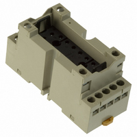
P7S-14F
Description
Contact OSTI
Manufacturer
Omron
Series
G7Sr
Type
Socketr
Specifications of P7S-14F
Number Of Positions
14
Mounting Type
DIN Rail
Termination Style
Screw Terminal
Socket Mounting
DIN Rail
Socket Terminals
Screw
Voltage Rating
24VDC
Rohs Compliant
Yes
Lead Free Status / RoHS Status
Lead free / RoHS Compliant
For Use With/related Products
G7S Series
For Use With
Z2362 - RELAY SAFETY 6A 24VDC PLUG-INZ2363 - RELAY SAFETY 6A 24VDC PLUG-IN
Lead Free Status / RoHS Status
Lead free / RoHS Compliant
Other names
P7S14F
Z2417
Z2417
Available stocks
Company
Part Number
Manufacturer
Quantity
Price
Company:

Part Number:
P7S-14F
Manufacturer:
Omron Electronics Inc-EMC Div
Quantity:
135


C Circuit Design
A Load Circuits
C-A-1 Load Switching
In actual Relay operation, the switching capacity, electrical durability,
and applicable load will vary greatly with the type of load, the
ambient conditions, and the switching conditions. Confirm operation
under the actual conditions in which the Relay will be used.
A Resistive Loads and Inductive Loads
The switching power for an inductive load will be lower than the
switching power for a resistive load due to the influence of the
electromagnetic energy stored in the inductive load.
B Switching Voltage (Contact Voltage)
The switching power will be lower with DC loads than it will with AC
loads. Applying voltage or current between the contacts exceeding
the maximum values will result in the following:
1. The carbon generated by load switching will accumulate around
2. Contact deposits and locking will cause contacts to malfunction.
C Switching Current (Contact Current)
Current applied to contacts when they are open or closed will have a
large effect on the contacts. For example, when the load is a motor or
a lamp, the larger the inrush current, the greater the amount of
contact exhaustion and contact transfer will be, leading to deposits,
locking, and other factors causing the contacts to malfunction.
(Typical examples illustrating the relationship between load and
inrush current are given below.) If a current greater than the rated
current is applied and the load is from a DC power supply, the
connection and shorting of arcing contacts will result in the loss of
switching capability.
DC Loads and Inrush Current
the contacts and cause deterioration of insulation.
Resistive load
Incandescent bulb
(approx. 6 to 11 times
steady-state current)
http://www.ia.omron.com/
Relay,
solenoid
Motor
(approx. 5 to
10 times steady-
state current)
Time (t)
AC Loads and Inrush Current
C-A-2 Electrical Durability
Electrical durability will greatly depend on factors such as the coil
drive circuit, type of load, switching frequency, switching phase, and
ambient atmosphere. Therefore be sure to check operation in the
actual application.
C-A-3 Failure Rates
The failure rates provided in this catalog are determined through
tests performed under specified conditions. The values are reference
values only. The values will depend on the operating frequency, the
ambient atmosphere, and the expected level of reliability of the
Relay. Be sure to check relay suitability under actual load conditions.
Solenoid
Incandes-
cent bulb
Motor
Relay
Capacitor
Resistive
load
Coil drive circuit
Type of load
Switching frequency
Switching phase
(for AC load)
Ambient atmosphere
Type of load Ratio of
(c)Copyright OMRON Corporation 2007 All Rights Reserved.
Approx.
10
Approx.
10 to 15
Approx.
5 to 10
Approx.
2 to 3
Approx.
20 to 50
1
current
steady-
current
inrush
state
to
Rated voltage applied to coil using
instantaneous ON/OFF
Rated load
According to individual ratings
Random ON, OFF
According to JIS C5442 standard test
conditions
Waveform
Steady-
state
current
C-5
Related parts for P7S-14F
Image
Part Number
Description
Manufacturer
Datasheet
Request
R

Part Number:
Description:
SOCKET PC MNT FOR G7S RELAY
Manufacturer:
Omron
Datasheet:

Part Number:
Description:
Relay Sockets & Hardware G7 RELAY TRACK MT SOCKET
Manufacturer:
Omron
Datasheet:

Part Number:
Description:
Relay Sockets & Hardware G7 relay PCB mounting
Manufacturer:
Omron
Part Number:
Description:
Relay Sockets & Hardware SOCKET
Manufacturer:
Omron
Datasheet:

Part Number:
Description:
G6S-2GLow Signal Relay
Manufacturer:
Omron Corporation
Datasheet:
Part Number:
Description:
Compact, Low-cost, SSR Switching 5 to 20 A
Manufacturer:
Omron Corporation
Datasheet:
Part Number:
Description:
Manufacturer:
Omron Corporation
Datasheet:
Part Number:
Description:
Manufacturer:
Omron Corporation
Datasheet:
Part Number:
Description:
Manufacturer:
Omron Corporation
Datasheet:
Part Number:
Description:
Manufacturer:
Omron Corporation
Datasheet: