P7S-14F Omron, P7S-14F Datasheet - Page 12
P7S-14F
Manufacturer Part Number
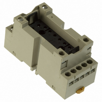
P7S-14F
Description
Contact OSTI
Manufacturer
Omron
Series
G7Sr
Type
Socketr
Specifications of P7S-14F
Number Of Positions
14
Mounting Type
DIN Rail
Termination Style
Screw Terminal
Socket Mounting
DIN Rail
Socket Terminals
Screw
Voltage Rating
24VDC
Rohs Compliant
Yes
Lead Free Status / RoHS Status
Lead free / RoHS Compliant
For Use With/related Products
G7S Series
For Use With
Z2362 - RELAY SAFETY 6A 24VDC PLUG-INZ2363 - RELAY SAFETY 6A 24VDC PLUG-IN
Lead Free Status / RoHS Status
Lead free / RoHS Compliant
Other names
P7S14F
Z2417
Z2417
Available stocks
Company
Part Number
Manufacturer
Quantity
Price
Company:

Part Number:
P7S-14F
Manufacturer:
Omron Electronics Inc-EMC Div
Quantity:
135


C-A-6 Connecting Loads for Multi-pole Relays
Connect multi-pole Relay loads according to diagram "a" below to
avoid creating differences in electric potential in the circuits. If a
multi-pole Relay is used with an electric potential difference in the
circuit, it will cause short-circuiting due to arcing between contacts,
damaging the Relays and peripheral devices.
C-A-7 Motor Forward/Reverse Switching
Switching a motor between forward and reverse operation creates an
electric potential difference in the circuit, so a time lag (OFF time)
must be set up using multiple Relays.
C-A-8 Power Supply Double Break with Multi-pole
If a double break circuit for the power supply is constructed using
multi-pole Relays, take factors into account when selecting models:
Relay structure, creepage distance, clearance between unlike poles,
and the existence of arc barriers. Also, after making the selection,
check operation in the actual application. If an inappropriate model is
selected, short-circuiting will occur between unlike poles even when
the load is within the rated values, particularly due to arcing when
power is turned OFF. This can cause burning and damage to
peripheral devices.
C-A-9 Short-circuiting Due to Arcing between NO and
With Relays that have NO and NC contacts, short-circuiting between
contacts will result due to arcing if the space between the NO and
NC contacts is too small or if a large current is switched.
Do not construct a circuit in such a way that overcurrent and burning
occur if the NO, NC, and SPDT contacts are short-circuited.
Example of Incorrect Circuit
Example of Correct Circuit
Arc short-circuiting occurs.
Power
supply
a. Correct Connection
X
X
X
X
1
2
2
1
Relays
NC Contacts in SPDT Relays
Load
M
Load
M
Load
B
http://www.ia.omron.com/
B
Load
Incorrect
Correct
Motor
Power
supply
b. Incorrect Connection
X
X
1
2
Load
Forward
operation
Load
ON
OFF
time
Load
operation
Reverse
ON
OFF
time
Load
operation
Forward
ON
C-A-10 Using SPST-NO/SPST-NC Contact Relays as an
Do not construct a circuit so that overcurrent and burning occur if the
NO, NC and SPDT contacts are short-circuited. Also, with SPST-NO/
SPST-NC Relays, a short-circuit current may flow for forward/reverse
motor operation.
C-A-11 Connecting Loads of Differing Capacities
Do not have a single Relay simultaneously switching a large load and
a microload. The purity of the contacts used for microload switching
will be lost as a result of the contact spattering that occurs during
large load switching, and this may give rise to contact failure during
microload switching.
B Input Circuits
C-B-1 Maximum Allowable Voltage
The coil's maximum allowable voltage is determined by the coil
temperature increase and the heat withstand temperature of the
insulation material. (If the heat withstand temperature is exceeded, it
will cause coil burning and layer shorting.) There are also important
restrictions imposed to prevent problems such as thermal changes
and deterioration of the insulation, damage to other control devices,
injury to humans, and fires, so be careful not to exceed the specified
values provided in this catalog.
C-B-2 Voltage Applied to Coils
Apply only the rated voltage to coils. The Relays will operate at the
must-operate voltage or greater, but the rated voltage must be
applied to the coils in order to obtain the specified performance.
C-B-3 Changes in Must-operate Voltage Due to Coil
It may not be possible to satisfy this catalog values for must-operate
voltages during a hot start or when the ambient temperature exceeds
23°C, so be sure to check operation under the actual application
conditions.
Coil resistance is increased by a rise in temperature causing the
must-operate voltage to increase. The resistance thermal coefficient
of a copper wire is approximately 0.4% per 1°C, and the coil
resistance also increases at this percentage.
This catalog values for the must-operate voltage and must-release
voltage are given for a coil temperature of 23°C.
Example of incorrect circuit
Example of correct circuit
X
1
(c)Copyright OMRON Corporation 2007 All Rights Reserved.
SPDT Relay
Temperature
Load
Load
Arc short-circuiting occurs.
X
2
Power supply
(Short-circuit current)
Incorrect
Correct
X
X
1
2
L
ON
OFF time
ON
C-7
Related parts for P7S-14F
Image
Part Number
Description
Manufacturer
Datasheet
Request
R

Part Number:
Description:
SOCKET PC MNT FOR G7S RELAY
Manufacturer:
Omron
Datasheet:

Part Number:
Description:
Relay Sockets & Hardware G7 RELAY TRACK MT SOCKET
Manufacturer:
Omron
Datasheet:

Part Number:
Description:
Relay Sockets & Hardware G7 relay PCB mounting
Manufacturer:
Omron
Part Number:
Description:
Relay Sockets & Hardware SOCKET
Manufacturer:
Omron
Datasheet:

Part Number:
Description:
G6S-2GLow Signal Relay
Manufacturer:
Omron Corporation
Datasheet:
Part Number:
Description:
Compact, Low-cost, SSR Switching 5 to 20 A
Manufacturer:
Omron Corporation
Datasheet:
Part Number:
Description:
Manufacturer:
Omron Corporation
Datasheet:
Part Number:
Description:
Manufacturer:
Omron Corporation
Datasheet:
Part Number:
Description:
Manufacturer:
Omron Corporation
Datasheet:
Part Number:
Description:
Manufacturer:
Omron Corporation
Datasheet: