BF-1 Omron, BF-1 Datasheet - Page 33
BF-1
Manufacturer Part Number
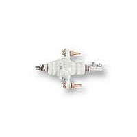
BF-1
Description
ELECTRODE HOLDER
Manufacturer
Omron
Datasheet
1.PFC-N8.pdf
(72 pages)
Specifications of BF-1
Description/function
General and industrial use electrode holder
Equipment Type
Electrode Holder
Lead Free Status / RoHS Status
Lead free / RoHS Compliant
Lead Free Status / RoHS Status
Lead free / RoHS Compliant


61F-UHS/HSL
External Circuit Diagrams (Example)
61F-UHS
Automatic Operation for Water Supply and Drainage
1. Water Supply
•
•
61F-UHS
Socket:
Operation: When the water level reaches E1, the pump stops
and, when the water level reaches E2 or below, the pump starts.
Connection: Connect the contactor coil terminal to terminal 2 of
the plug-in model. (Terminal 3 is not used.)
200-VAC power supply
8PFA1 (track mounted)/
PL08 (back connecting)
R S T
3
Be sure to ground terminal 1.
2
E
3
4
1
E
2
M
5
8
E
Water supply
MCCB
1
THR
6
7
Pump OFF
Pump ON
Contactor
P
P
Power
source
E
Reservoir
1
E
2
E
3
Water tank
7
6
200 V
0 V
61F-HSL
E
Socket:
3
5
E
8
2
E
24 V
24 V
1
Control circuit
(--)
3
8PFA (track mounted)/
PL08 (back connecting)
2
PS-3S
4
1
4
1
2. Water Drainage
•
•
61F-UHS
5
8
Operation: When the water level reaches E1, the pump starts
and, when the water level reaches E2 or below, the pump stops.
Connection: Connect the contactor coil terminal to terminal 3 of
the plug-in model. (Terminal 2 is not used.)
6
7
Note: The diagram shows the connections for the water supply.
Stop
Start
U
3
2
(+)
U
When draining, change the connection from terminal 2 to
terminal 3.
Power
source
E
1
E
2
E
3
Water drainage
Pump ON
Pump OFF
P
61F-UHS/HSL
Related parts for BF-1
Image
Part Number
Description
Manufacturer
Datasheet
Request
R

Part Number:
Description:
G6S-2GLow Signal Relay
Manufacturer:
Omron Corporation
Datasheet:
Part Number:
Description:
Compact, Low-cost, SSR Switching 5 to 20 A
Manufacturer:
Omron Corporation
Datasheet:
Part Number:
Description:
Manufacturer:
Omron Corporation
Datasheet:
Part Number:
Description:
Manufacturer:
Omron Corporation
Datasheet:
Part Number:
Description:
Manufacturer:
Omron Corporation
Datasheet:
Part Number:
Description:
Manufacturer:
Omron Corporation
Datasheet:
Part Number:
Description:
Manufacturer:
Omron Corporation
Datasheet:
Part Number:
Description:
Manufacturer:
Omron Corporation
Datasheet: