BF-1 Omron, BF-1 Datasheet - Page 11
BF-1
Manufacturer Part Number
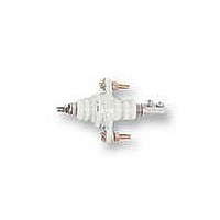
BF-1
Description
ELECTRODE HOLDER
Manufacturer
Omron
Datasheet
1.PFC-N8.pdf
(72 pages)
Specifications of BF-1
Description/function
General and industrial use electrode holder
Equipment Type
Electrode Holder
Lead Free Status / RoHS Status
Lead free / RoHS Compliant
Lead Free Status / RoHS Status
Lead free / RoHS Compliant


61F-Gj
61F-G1
Application 1:Automatic Water Supply Control with Pump Idling Prevention
Note: Be sure to ground terminal E3.
Pump OFF
Pump ON
Water
supply
P
Water tank
Short-
age
B
Water supply
source
E
200-VAC power supply
E
1
’
1
E
L
MCCB
2
E
’
2
E
THR
E
3
3
’
R S T
(U
(U
1
1
(U
(U
indicator ON)
indicator OFF)
2
2
Electromagnetic
switch
indicator ON)
indicator OFF)
M
61F-G1
Water supply
source
P
Rated voltage:
S0- -S1: 100 or 110 or 120 VAC
S0- -S2: 200 or 220 or 240 VAC
200 V
100 V
S
*
0
S
0 V
1
E
3
U
E
2
S
2
Transformer
2
’
Tb
E
1
24 V
’
24 V
1
8 V
E
3
U
Ta
2
1
61F-11
Relay Unit
61F-11
Relay Unit
E
2
•
•
•
E
U
1
The pump stops (U2 indicator ON) when the water level reaches
E1 and the pump starts (U2 indicator OFF) when the water level
in the tank drops below E2.
When the level of the water supply source drops below E2’, the
pump stops (U1 indicator OFF). Pump idling is prevented and the
alarm sounds.
Insert a pushbutton switch (NO contact) between E1’ and E3 as
shown by the dotted line. When starting the pump or after
recovering from a power failure, if the water supply source level
has not yet reached E1’, press the pushbutton switch to start the
pump by momentarily short-circuiting E1’ and E3. When the
pump stops during normal operation subsequent to an alarm
issued for a low water level (e.g., the water level does not reach
E2’), do not press the pushbutton switch.
U
1
Tc
Water tank
U
U
1
1
2
2
E
2
’
B
Tb
2
E
(E
Alarm
1
4
’
)
E
3
E
2
E
1
Push-
button
switch
PS-3S
61F-Gj
Related parts for BF-1
Image
Part Number
Description
Manufacturer
Datasheet
Request
R

Part Number:
Description:
G6S-2GLow Signal Relay
Manufacturer:
Omron Corporation
Datasheet:
Part Number:
Description:
Compact, Low-cost, SSR Switching 5 to 20 A
Manufacturer:
Omron Corporation
Datasheet:
Part Number:
Description:
Manufacturer:
Omron Corporation
Datasheet:
Part Number:
Description:
Manufacturer:
Omron Corporation
Datasheet:
Part Number:
Description:
Manufacturer:
Omron Corporation
Datasheet:
Part Number:
Description:
Manufacturer:
Omron Corporation
Datasheet:
Part Number:
Description:
Manufacturer:
Omron Corporation
Datasheet:
Part Number:
Description:
Manufacturer:
Omron Corporation
Datasheet: