BF-1 Omron, BF-1 Datasheet
BF-1
Specifications of BF-1


Related parts for BF-1

BF-1 Summary of contents
Page 1
Floatless Level Controller Automatic Water Supply and Drainage Control Ideal for level control of any conductive liquid Both general-purpose and panel-use models available Incorporates an arrester for surge and induced lightning protection Wide range of models: Long-distance, high- and low-sensitivity, ...
Page 2
Model Selection Basic Configuration of 61F Conductive Level Controller To use a 61F Conductive Level Controller, the 61F itself, Electrode Holders, and Electrodes are required. 61F Basic configuration Electrode Holders Electrodes Typical Application Example 61F Controller Cermet wire is ...
Page 3
Controller Selection Guide by Application Item A t Automatic water supply and drainage control Function Automatic pump operation (constant water level) Water level --- indication abnormal alarm Appearance Standard Model 61F-G (Pages 6 to 10, 52) Item Function ...
Page 4
Item Water source level indication, prevention of pump idling due to water shortage, automatic water supply control, and indication of water level in tank Function Automatic pump Elevated water tank operation (constant water level) Water level Elevated water tank ...
Page 5
... Applications specific where high where high resistance mounting temperature/ strength is high pressure required conditions are severe BF-1 BF-3/-4/-5 BS-1 Sodium hydroxide, Sea water, ammonia acetic acid, dilute water, nitric acid sulfuric acid, dilute hydrochloric acid F03-60 HAS B F03-60 HAS C F03-11 ...
Page 6
Specifications Standard Models Specifications Items General-purpose Controller 61F-j (TDL) (see note 1 and 2) Controlling materials For control of or- and operating dinary purified conditions water or sewage water Supply voltage 100, 110, 120, 200, 220, 230 or 240 ...
Page 7
Internal Circuit Diagrams The schematic diagrams shown below typify the internal connections of the various 61F models. The designations Ta, Tb, and Tc (sometimes referred to collectively as “U”) may occur more than once in a product, however, the ...
Page 8
Note: The 61F-11H relay de-energizes when there is water present across the Electrodes, whereas the 61F relay energizes when there is water present across the Electrodes. Also, the terminal connections of those Controllers provided with LED indicators differ from ...
Page 9
Connections 61F-G Automatic Water Supply and Drainage Control 1. Water Supply Water supply P (U indicator ON) Pump OFF E 1 Pump ON (U indicator OFF • Connect electromagnetic switch coil terminal A to Tb. ...
Page 10
Two-wire Automatic Water Supply and Drainage Control 1. Water Supply Water supply P (U indicator ON) Pump OFF E 1 Pump ON (U indicator OFF • Connect electromagnetic switch coil terminal A to Tb. ...
Page 11
Application 1:Automatic Water Supply Control with Pump Idling Prevention Water tank (U indicator ON) 1 ’ indicator OFF ’ Short- age 3 E ’ Water supply source Water supply P ...
Page 12
Application 2: Automatic Water Supply Control with Abnormal Water Shortage Alarm Water tank Water supply P (U indicator ON) Pump OFF Pump ON (U indicator OFF indicator OFF ...
Page 13
Automatic Drainage Control and Water Supply with Abnormal Water Increase Alarm 1. Drainage Water drainage indicator ON) 1 Upper E 4 limit (U indicator ON Pump ON (U indicator OFF ...
Page 14
Automatic Water Supply and Drainage Control with Abnormal Water Shortage Alarm and Water Tank Repletion 1. Water Supply Water supply Upper P limit (U indicator ON Pump OFF (U indicator ON) 2 ...
Page 15
Water Source Level Indication, Prevention of Pump Idling Due to Water Shortage, Automatic Water Supply Control, and Indica- tion of Water Level in Tank • Insert four Electrodes in the water supply source and five Electrodes in the ...
Page 16
Connection with Three-phase Four-line Circuit When supplying power from N-phase to the Controller in three-phase four-line circuit, refer to the following diagrams. Line voltage (R-S, S-T, or R-T): 380 or 415 VAC Phase voltage (N-R, N-S, or N-T): 220 ...
Page 17
Liquid Level Indication and Alarm B L Upper H (U indicator ON) 1 limit indicator OFF Middle (U indicator ON) 2 Lower limit (U indicator OFF) 2 ...
Page 18
Compact Plug-in Models (11-pin Type) Specifications Item General-pur- pose Controller 61F-GP-N Controlling materials For control of and operating ordinary purified conditions water or sew- age water Supply voltage 24, 100, 110, 120, 200, 220, 230 or 240 VAC; 50/60 ...
Page 19
Internal Circuit Diagrams 61F-GP-N/-NT/-NL/-ND Power supply Control circuit ...
Page 20
Connection with Three-phase Four-line Circuit When supplying power from N-phase to the Controller in three-phase four-line circuit, refer to the following diagrams. Line voltage (R-S, S-T, or R-T): 380 or 415 VAC Phase voltage (N-R, N-S, or N-T): 220 ...
Page 21
Compact Plug-in Models (8-pin Type) Specifications Item General-pur- Long-distance pose Controller 61F-GP-N8 61F-GP-N8Y 2KM (for 2 km) (see note 1) 4KM (for 4 km) Controlling For control of or- For control of or- materials and dinary purified dinary purified ...
Page 22
Internal Circuit Diagrams 61F-GP-N8/-N8L/-N8D/-N8HY Power supply Control circuit (see note) Note for the 61F-GP-N8HY. 61F-GP-N8Y Power supply Control circuit 61F-GP-N8H Power supply 24 V Control circuit 24 V 61F-GP-N8-V50 ...
Page 23
Connections 61F-GP-N8 Automatic Water Supply and Drainage Control 1. Water Supply Water supply P Indicator ON Pump OFF E 1 Pump ON Indicator OFF • Connect electromagnetic switch coil terminal A to terminal 2. • ...
Page 24
Connection with Three-phase Four-line Circuit When supplying power from N-phase to the Controller in three-phase four-line circuit, refer to the following diagrams. Line voltage (R-S, S-T, or R-T): 380 or 415 VAC Phase voltage (N-R, N-S, or N-T): 220 ...
Page 25
Plug-in Models Specifications Item General-purpose Controller 61F-G1P 61F-G2P 61F-IP Controlling materials For control of ordinary and operating purified water or sewage conditions water Supply voltage 100, 110, 120, 200, 220, 230 or 240 VAC; 50/60 Hz Operating voltage range ...
Page 26
Internal Circuit Diagrams 61F-G1P/-G1PL/-G1PD Control circuit Power Control circuit supply ...
Page 27
Connections 61F-G1P Application 1: Automatic Water Supply Control with Pump Idling Prevention Water supply Water tank source Water supply P Pump E 1 OFF ’ ’ Short- Pump age 3 E ’ ...
Page 28
Application 2: Automatic Water Supply Control with Abnormal Water Shortage Alarm Water tank Water supply Water drainage P Pump OFF E 1 Pump Shortage 200-VAC power supply R S ...
Page 29
Automatic Drainage Control with Abnormal Water Increase Alarm Application 1: Drainage Water drainage B L Upper E 4 limit Pump Pump OFF 200-VAC power supply Electromagnetic switch ...
Page 30
Application 2: Water Supply Water supply Upper L P limit E 4 Pump OFF E 1 Pump 200-VAC power supply MCCB Contactor THR P M Note: Be sure to ground ...
Page 31
Liquid Level Indication and Alarm B L Upper H limit Middle Lower limit E 3 200-VAC power supply MCCB P M Note: Be sure to ground ...
Page 32
Ultra High-sensitivity Models Use these models for sensing objects such as ice, high-purity distilled water, moisture, or other objects with low electrical conductivity. Specifications Item Supply voltage 100, 200, or 220 VAC; 50/60 Hz Operating voltage range 85% to ...
Page 33
External Circuit Diagrams (Example) 61F-UHS Power 4 5 source Socket: 8PFA1 (track mounted)/ PL08 (back connecting) 61F-UHS Automatic Operation for Water Supply and Drainage 1. Water Supply ...
Page 34
Solid-state Alternate Operation Relay When operating two pumps alternately for controlling the one-point liquid level, use the Relay in combination with 61F Controller. 61F-APN2 Compact Plug-in Model Specifications Ratings Supply voltage 100, 110, 200, 220 VAC; 50/60 Hz ...
Page 35
Connect the output terminal Ta of the 61F-Gj to input terminal 2 of the 61F-APN2. Connection Connect the contactor coil terminal A to the switching contact terminals 3 and 4 of the 61F-APN2. Operation of the two pumps can ...
Page 36
Connections At 200 VAC Water Supply (When Combined with 61F-G) The relay operation can be monitored if indicators are connected as shown by the dotted line. To power source T 200-VAC power source 61F-APN2 MCCB ...
Page 37
Water Supply (When Combined with 61F-G1) The relay operation can be monitored if indicators are connected as shown by the dotted line. To power source T 200-VAC power source 61F-APN2 6 5 ...
Page 38
Water Drainage (When Combined with 61F-G2) The relay operation can be monitored if indicators are connected as shown by the dotted line. To power source T 200-VAC power source 61F-APN2 6 5 MCCB ...
Page 39
Water Supply (When Combined with 61F-G3) The relay operation can be monitored if indicators are connected as shown by the dotted line. To power source T 200-VAC power source 61F-APN2 6 MCCB 7 Contactor ...
Page 40
Water Supply (When Combined with 61F-G4) The relay operation can be monitored if indicators are connected as shown by the dotted line. To power source T 200-VAC power supply 61F-APN2 6 5 ...
Page 41
At 220 VAC Water Supply (When Combined with 61F-G1P) For example, operation indication is possible by the connection as shown by the dotted line. Power source 220 VAC 61F-APN2 ...
Page 42
Water Supply (When Combined with 61F-GP-N) For example, operation indication is possible by the connection as shown by the dotted line. Power source 220-VAC 61F-APN 6 Knife switch 7 A Electromagnetic switch 1 ...
Page 43
Water Drainage (When Combined with 61F-G2P) For example, operation indication is possible by the connection as shown by the dotted line. Power source 220-VAC 61F-ANP2 Knife switch Electronic circuit ...
Page 44
Surge Suppressor Unit A high-capacity protective device is available which protects 61F-series Floatless Level Controllers against faults arising from electrical surges (such as indirect strokes of lightning) when the Controllers are employed in elevated water tanks or in ...
Page 45
... Screw Flange Ceramics 150°C max. (without water drips or vapor on the surface of the Electrode Holder) PS-31 BF-1 (see note 2) --- BF-1 PS-31 --- --- --- --- --- When corrosion When Electrode positions resistance is required. are distant from water Since Teflon is used as surface. ...
Page 46
Note: 1. The BS-1 and BS-1T are pressure-proof models. The rest of models are not pressure-proof. 2. The BS-1 that uses SUS304 for clamping sections and screws of PT1/2 specifications is called BS-1S1. 3. The BS-1 that uses SUS304 ...
Page 47
... When the required length of Electrode is more than 1 m, use a Sepa- Model rator at each joint of two Electrodes prevent the Electrodes from contacting one another. Use a one-pole type for BF Electrodes. The five-pole type can be used for PS-5S and PS-4S Electrodes. Material: Ceramic Separator ...
Page 48
... Use this Cover for PS-series Electrode Holders with Mounting Frames (upper one in the following illustration), This Cover can also be used when installing the BF-series Electrode Holders outdoors. Since this Cover is not water-proof, water or dust may enter through the wire hole (lower one below) ...
Page 49
Installing PS-jS Electrode Holder on Tank 1. For tanks with thin walls combined with the F03-12 Spring Clamps 1. Using the F03- nut Tank 2. Using the F03- flange 2. For tanks with thick metal ...
Page 50
Electrode Holder and Electrodes How to Mount Electrodes Connecting Electrodes to Electrode Holders Electrode Holder Clamp screw 3. Tighten the Electrode with the two clamp screws. (see note) Connecting nut 1. Spin a locknut and a spring Spring washer ...
Page 51
Electrode Bands Connecting Electrode Holder and Electrode Band Connect the connecting nut to the Electrode section as shown in the illustration below and secure the connecting nut with the clamp screw. Insert the Electrode Band into the lower hold ...
Page 52
... Holder and attach the two cap screws (M5 x 25) supplied with the F03-11 Protective Cover. Next, put the Protective Cover over the top of the BF-series Elec- trode Holder, and then tighten the supplied two screws ( with washers). Refer to the following illustration. ...
Page 53
Four, 6-dia holes 61F-G4 Four, 6-dia holes Plug-in Models 61F-GP-N 61F-GP-N8 M3 screw Mounting Holes Four, 6-dia mounting holes Mounting Holes M3 screw Four, 6-dia mounting holes 61F- GP-N PF113A-E 61F- GP-N8 PF083A-E 61F 91 ...
Page 54
Ultra High-sensitivity Models 61F-UHS 61F-HSL Solid-state Alternate Operation Relay 61F-APN2 Surge Suppressor Unit 61F-03B 61F-04B 61F 61F-G1P 61F-G2P 61F-IP 14PFA 8PFA1 8PFA 61F- APN2 PF083A-E 61F-03B 61F-04B PF0113A-E ...
Page 55
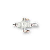
... Note: The PS-3SR, PS-4SR, and PS-5SR have built-in resistor of 6.8 kΩ and used for the two-wire 61F models. PS-31 Weight: approx. 325 g Electrode SUS304 F03-31 Dust-preventive rubber cap (optional) Weight: approx BF-1 Weight: approx. 125 g 34 dia. PS-3S (approx. 150 g) PS-4S (approx. 170 g) PS-3SR (approx. 155 g) PS-4SR (approx. 175 g) ...
Page 56
... Weight Approx BF-3 Weight: approx. 420 g BF-3R Weight: approx. 425 g Two, 6-dia. holes Three, 26-dia. holes BF-4 Weight: approx. 520 g BF-4R Weight: approx. 525 g Four, 26-dia. holes Two, 6-dia. holes BF-5 Weight: approx. 710 g BF-5R Weight: approx. 715 g Five, 26-dia. holes 110 dia ...
Page 57
PH-1 (Approx. 140 g with a 1-m cord) Resin 19 dia. Cable OD: Vinyl 5.0 dia., Chloroprene 6.5 dia. Note: Cable is supplied in lengths 10, 15, 20, 30, 40, 50, 60, 70, 80, 90, or ...
Page 58
Connecting Sockets Available Models Model No. of Controller Unit 61F-UHS 61F-HSL 61F-APN2 61F-G1P 61F-G2P 61F-IP 61F-GP-N 61F-GPN-V50 61F-GP-N8 61F-03B 61F-04B Track-mounted Sockets PF083A-E Eight, M3 sems screws 52 max. 41 max. 8PFA Eight, M3 sems ...
Page 59
Fourteen, M3 sems screws 52 max. 72 max. M3.5 x 11.5 sems screws for terminal screws PF113A-E Eleven, M3 sems screws 52 max. Back-connecting Sockets PL08 50.5 max. 35 max. PL11 51 max. 35 ...
Page 60
PL15 66 max. Terminal Arrangement/ Internal Connections (Top View) 16 max. Two 2-dia. holes 41 max. 22 max. 45 max. 61F Mounting Holes Two, 3.5 dia Controller Unit mounting holes Two, 3.5-dia Socket mounting holes ...
Page 61
Mounting Brackets When the 61F-G1P/-G2P/-IP/-UHS/-HSL is mounted with a Track-mounted Socket, the Controller is held secure by Mounting Brackets at- tached to the Socket. 61F-GP-N To mount the 61F-GP-N or 61F-GPN-V50 on the PF113A-E Track- mounted Socket, use the ...
Page 62
DIN Track Mounting Accessories DIN Track PFP-100N PFP-50N (see note 1) (see note 1) (see note 2) DIN Track PFP-100N2 (see note 2) Note: 1. The PFP-100N both ends, while the PFP50N ...
Page 63
Connection with SE Motor Protective Relay Prevents Burnouts in Motors and Pumps Connection Example (When Combined with 61F-G) Power source Model SET-3 current converter + -- Static relay for protection of motors and pumps against problems ...
Page 64
Application Examples • Level control in tanks, reservoirs, sewage plants, underground wells, mixing plants etc. • Level control for element protection in pipes, channels, and irrigation systems. • Flow detection in pipes, channels, and irrigation systems. • Ice bank ...
Page 65
Precautions ! WARNING Never touch any of the terminals. Doing so may result in elec- tric shock. Never attempt to disassemble the 61F or touch the inside of the 61F while the power is being supplied. Doing so may ...
Page 66
... When mounting a BS-1 Electrode Holder to a boiler, wrap Teflon tape times around the mounting position and use the gasket supplied. Always apply the F03-11 Protective Cover if the BF-3 (-4 or -5) is used outside position subject to water splashes or where dust or dirt can settle. Foreign matter on the Electrode insulation can cause electrical leakage and malfunctions ...
Page 67
Inspecting the Electrode Circuits In cases where the Electrodes cannot be withdrawn to test the Elec- trode circuit, a tester can be used to measure the resistance be- tween the Electrode and ground, as shown in the diagram below. ...
Page 68
Water Leak Alarm/Detector Eliminate Problems Caused from Water Leakage kΩ variable operating resistance to detect virtually any liquid. Two types available: Water Leak Alarm (61F-WLA) and plug-in Water Leak Detector (61F-GPN-V50). 24 VAC interelectrode voltage causes no ...
Page 69
Operation Internal Circuit 61F-GPN-V50 Water Leak Detector AC power source Operating Principle When the two conductive cores of the Sensor Cable are contacted by a liquid, a weak alternating current (as small max.) flows across the ...
Page 70
Dimensions Note: All units are in millimeters unless otherwise indicated. 61F-WLA Water Leak Alarm 61F-GPN-V50 Water Leak Detector Accessories (Order Separately) Connecting Sockets (for 61F-GPN-V50 Water Leak Detector) PF113A-E Track-mounted Socket Eleven, M3 sems screws 52 max. ...
Page 71
Installation Connections 61F-WLA Water Leak Alarm Fuse Rectifica- tion/ smoothing circuit Rectifica- tion/ smoothing circuit Test switch 100, 110, 120 VAC power source 200, 220, 240 VAC power source Precautions Correct Use (1) Use only F03-15 or F03-16 Sensor ...
Page 72
... OMRON ELECTRONICS LLC One East Commerce Drive Schaumburg, IL 60173 1-800-55-OMRON Cat. No. F030-E1-8 OMRON ON- -LINE Global -- http://www.omron.com USA -- http://www.omron.com/oei Canada -- http://www.omron.com/oci Specifications subect to change without notice 61F-WLA/-GPN-V50 OMRON CANADA, INC. 885 Milner Avenue Toronto, Ontario M1B 5V8 416-286-6465 Printed in U.S.A. ...