BF-1 Omron, BF-1 Datasheet - Page 17
BF-1
Manufacturer Part Number
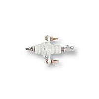
BF-1
Description
ELECTRODE HOLDER
Manufacturer
Omron
Datasheet
1.PFC-N8.pdf
(72 pages)
Specifications of BF-1
Description/function
General and industrial use electrode holder
Equipment Type
Electrode Holder
Lead Free Status / RoHS Status
Lead free / RoHS Compliant
Lead Free Status / RoHS Status
Lead free / RoHS Compliant


61F-I
61F-I
Liquid Level Indication and Alarm
Note: Be sure to ground terminal E3.
B
B
L
L
L
M
L
H
Upper
Middle
Lower
limit
limit
200-VAC power supply
MCCB
E
1
E
2
R S T
E
3
(U
(U
(U
(U
M
1
1
2
2
61F-I
indicator ON)
indicator OFF)
indicator ON)
indicator OFF)
P
0 V
100 V
200 V
Alarm
Water supply source
U
Rated voltage:
S0--S1: 100 or 110 or 120 VAC
S0--S2: 200 or 220 or 240 VAC
2
Tc
S
0
B
Transformer
24 V
24 V
8 V
Intermediate
B
U
S
1
1
PL
U
61F-11
Relay Unit
Upper limit
61F-11
Relay Unit
L
1
3
S
2
PL
U
L
2
2
E
L
1
3
PL
U
U
Water tank
1
2
Lower
limit
•
•
•
E
2
When the water level drops below E2, the lower-limit indicator
turns ON and the alarm sounds (U2 indicator OFF).
When the water level reaches E2, the alarm turns OFF and the
intermediate indicator turns ON (U2 indicator ON).
When the water level rises to E1, the upper-limit indicator turns
ON and the alarm sounds (U1 indicator ON).
E
*
1
E
3
E
2
E
1
PS-3S
Upper alarm
Lower alarm
Intermediate
61F-I
Related parts for BF-1
Image
Part Number
Description
Manufacturer
Datasheet
Request
R

Part Number:
Description:
G6S-2GLow Signal Relay
Manufacturer:
Omron Corporation
Datasheet:
Part Number:
Description:
Compact, Low-cost, SSR Switching 5 to 20 A
Manufacturer:
Omron Corporation
Datasheet:
Part Number:
Description:
Manufacturer:
Omron Corporation
Datasheet:
Part Number:
Description:
Manufacturer:
Omron Corporation
Datasheet:
Part Number:
Description:
Manufacturer:
Omron Corporation
Datasheet:
Part Number:
Description:
Manufacturer:
Omron Corporation
Datasheet:
Part Number:
Description:
Manufacturer:
Omron Corporation
Datasheet:
Part Number:
Description:
Manufacturer:
Omron Corporation
Datasheet: