KAC-9618 Eastman Kodak Company, KAC-9618 Datasheet - Page 30
KAC-9618
Manufacturer Part Number
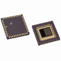
KAC-9618
Description
IC SENSOR IMAGE VGA MONO 48-CLCC
Manufacturer
Eastman Kodak Company
Type
CMOS Imagingr
Datasheet
1.KAC-9618.pdf
(43 pages)
Specifications of KAC-9618
Pixel Size
7.5µm x 7.5µm
Active Pixel Array
648H x 488V
Frames Per Second
30
Voltage - Supply
3.3V
Package / Case
48-CLCC
Lead Free Status / RoHS Status
Lead free / RoHS Compliant
Other names
LM9618IEA
LM9618IEA
LM9618IEA
Available stocks
Company
Part Number
Manufacturer
Quantity
Price
Company:

Part Number:
KAC-9618
Manufacturer:
IXYS
Quantity:
2 100


IMAGE SENSOR SOLUTIONS
Register Set
Register Name Digital Video Mode 0
Address
Mnemonic
Type
Reset Value
www.kodak.com/go/imagers 585-722-4385
7:6
5:4
3:0
Bit
PixDataSel
PixDataMsb
Bit Symbol
06 Hex
VMODE0
Read/Write
00 Hex
(continued)
Use to program the number of
active bits on the digital video bus
d[11:0], starting from the MSB
(d[11]). Inactive bits are tri-stated.:
Use to program the routing of the
MSB output of the internal video
A/D to a bit on the digital video
bus.
Reserved
00
01
10
11
00
01
10
11
12 bit mode, bits
d[11:0] of the digital
video bus are active.
This is the default.
10 bit mode, bits
d[11:2] of the digital
video bus are active.
8 bit mode, bits
d[11:4] of the digital
video bus are active.
Reserved.
A/D [11:0] -> d[11:0].
A/D [10:0] -> d[11:1]
A/D [9:0] -> d[11:2]
A/D [8:0] -> d[11:3]
Description
30
Register Name Digital Video Mode 1
Address
Mnemonic
Type
Reset Value
7
6
5
4
3
2
1
0
Bit
PixClkMode
VsyncMode
HsyncMode
PixClkPol
VsynPol
HsynPol
OddEvenEn
TriState
Bit Symbol
07 Hex
VMODE1
Read/Write
00 Hext
Assert to set the pclk to “data
ready mode”. Clear, the default, to
set pclk to “free running mode”.
Assert to set the vsync pin to
“pulse mode”. Clear (the default)
to set the vsync signal to “level
mode”.
Assert to force the hsync signal to
pulse for a minimum of four pixel
clocks at the end of each row.
Clear (the default) to force the
hsync signal to a level indicating
valid data within a row.
Assert to set the active edge of
the pixel clock to negative. Clear
(the default) to set the active edge
of the clock to positive.
Assert to force the vsync signal to
generate a logic 0 during a frame
readout (Level Mode), or a nega-
tive pulse at the end of a frame
readout (Pulse Mode). Clear (the
default) to force the vsync signal
to generate a logic 1 during a
frame readout (Level Mode), or a
negative pulse at the end of a
frame readout (Pulse Mode).
Assert to force the hsync signal to
generate a logic 0 during a row
readout (Level Mode), or a nega-
tive pulse at the end of a row
readout (Pulse Mode). Clear (the
default) to force the hsync signal
to generate a logic 1 during a row
readout (Level Mode), or a nega-
tive pulse at the end of a readout
(Pulse Mode).
Assert to force the vsync pin to act
as an odd/even field indicator.
Clear (the default) to force the
vsync pin to act as a vertical syn-
chronization signal.
Assert to tri-state all output signals
(data and control) on the digital
video port. Clear (default) to
enable all signals (data and con-
trol) on the digital video port.
Email:imagers@kodak.com
Description
Related parts for KAC-9618
Image
Part Number
Description
Manufacturer
Datasheet
Request
R

Part Number:
Description:
IC PROCESSOR IMAGE DGTL REALTIME
Manufacturer:
Eastman Kodak Company

Part Number:
Description:
HEADBOARD FOR KAC-9618
Manufacturer:
Eastman Kodak Company

Part Number:
Description:
HEADBOARD FOR KAC-9619
Manufacturer:
Eastman Kodak Company

Part Number:
Description:
HEADBOARD FOR KAC-9628
Manufacturer:
Eastman Kodak Company

Part Number:
Description:
HEADBOARD FOR KAC-9630
Manufacturer:
Eastman Kodak Company

Part Number:
Description:
HEADBOARD FOR KAC-9637
Manufacturer:
Eastman Kodak Company

Part Number:
Description:
HEADBOARD FOR KAC-9638
Manufacturer:
Eastman Kodak Company

Part Number:
Description:
HEADBOARD FOR KAC-9647
Manufacturer:
Eastman Kodak Company

Part Number:
Description:
HEADBOARD FOR KAC-9648
Manufacturer:
Eastman Kodak Company
Part Number:
Description:
HEADBOARD FOR KAC-9627
Manufacturer:
Eastman Kodak Company
Part Number:
Description:
KIT EVALUATION SENSOR KAC-9618
Manufacturer:
Eastman Kodak Company
Part Number:
Description:
KIT EVALUATION SENSOR KAC-9638
Manufacturer:
Eastman Kodak Company
Part Number:
Description:
KIT EVALUATION SENSOR KAC-9628
Manufacturer:
Eastman Kodak Company
Part Number:
Description:
KIT EVALUATION SENSOR KAC-9637
Manufacturer:
Eastman Kodak Company
Part Number:
Description:
KIT EVALUATION SENSOR KAC-9647
Manufacturer:
Eastman Kodak Company