KAC-9618 Eastman Kodak Company, KAC-9618 Datasheet - Page 28
KAC-9618
Manufacturer Part Number
KAC-9618
Description
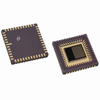
IC SENSOR IMAGE VGA MONO 48-CLCC
Manufacturer
Eastman Kodak Company
Type
CMOS Imagingr
Datasheet
1.KAC-9618.pdf
(43 pages)
Specifications of KAC-9618
Pixel Size
7.5µm x 7.5µm
Active Pixel Array
648H x 488V
Frames Per Second
30
Voltage - Supply
3.3V
Package / Case
48-CLCC
Lead Free Status / RoHS Status
Lead free / RoHS Compliant
Other names
LM9618IEA
LM9618IEA
LM9618IEA
Available stocks
Company
Part Number
Manufacturer
Quantity
Price
Company:

Part Number:
KAC-9618
Manufacturer:
IXYS
Quantity:
2 100


IMAGE SENSOR SOLUTIONS
Register Set
The following section describes all available registers in the
KAC-9618 register bank and their function.
Register Name Settings Update Register
Mnemonic
Address
Type
Reset Value
Register Name Device Rev Register
Mnemonic
Address
Type
www.kodak.com/go/imagers 585-722-4385
7:1
0
7:0
Bit
Bit
UpdateSettings
SiRev
Bit Symbol
Bit Symbol
UPDATE
00 Hex
Read/Write
00 Hex.
REV
01 Hex
Read Only.
(continued)
Reserved
Set to inform the integrated
timing and control circuit to
update the sensor with the
new settings. This bit is self
resetting. If this bit is set
anytime between the start of
vertical blanking until 4 rows
before the end of the frame
the values will take effect in
the next frame. If the update
bit is set from 3 rows before
end of frame until the start of
vertical blanking the registers
will either take effect in the
next frame or the frame after.
The silicon revision register.
Description
Description
28
Register Name Main Configuration 0
Address
Mnemonic
Type:
Reset Value
7
6
5
4
3
2
1
0
Bit
PwrUpBusy
PwrDown
BPCorrection
BlkLComp
BPmode
GainMode
Bit Symbol
02 Hex
MCFG0
Read/Write
00 Hex
(Read Only Bit)
Indicates that power on initializa-
tion is in progress. The sensor is
ready for use when this bit is at
logic 0.
Set to power down the sensor.
Writing a logic 1 to this register bit
has the same effect as taking the
pdwn pin high. Clear (the default)
this bit to power up the sensor.
Set to enable the bad pixel detec-
tion and correction circuit. Clear
(the default) to switch it off.
Set to disable the black level com-
pensation circuit. Clear (the
default) to switch it on.
Reserved
Set to configure the bad pixel cor-
rection circuit to operating in
monochrome mode (this should
be used with monochorme sen-
sors) Clear the (the default) to set
the bad pixel correction circuit to
operate in color mode (this should
be used with color sensors).
Reserved
Set to route all pixels to the green
gain amplifier. Clear (the default)
to route the green, green and blue
pixels to the green,green and blue
amplifiers.
Email:imagers@kodak.com
Description
Related parts for KAC-9618
Image
Part Number
Description
Manufacturer
Datasheet
Request
R

Part Number:
Description:
IC PROCESSOR IMAGE DGTL REALTIME
Manufacturer:
Eastman Kodak Company

Part Number:
Description:
HEADBOARD FOR KAC-9618
Manufacturer:
Eastman Kodak Company

Part Number:
Description:
HEADBOARD FOR KAC-9619
Manufacturer:
Eastman Kodak Company

Part Number:
Description:
HEADBOARD FOR KAC-9628
Manufacturer:
Eastman Kodak Company

Part Number:
Description:
HEADBOARD FOR KAC-9630
Manufacturer:
Eastman Kodak Company

Part Number:
Description:
HEADBOARD FOR KAC-9637
Manufacturer:
Eastman Kodak Company

Part Number:
Description:
HEADBOARD FOR KAC-9638
Manufacturer:
Eastman Kodak Company

Part Number:
Description:
HEADBOARD FOR KAC-9647
Manufacturer:
Eastman Kodak Company

Part Number:
Description:
HEADBOARD FOR KAC-9648
Manufacturer:
Eastman Kodak Company
Part Number:
Description:
HEADBOARD FOR KAC-9627
Manufacturer:
Eastman Kodak Company
Part Number:
Description:
KIT EVALUATION SENSOR KAC-9618
Manufacturer:
Eastman Kodak Company
Part Number:
Description:
KIT EVALUATION SENSOR KAC-9638
Manufacturer:
Eastman Kodak Company
Part Number:
Description:
KIT EVALUATION SENSOR KAC-9628
Manufacturer:
Eastman Kodak Company
Part Number:
Description:
KIT EVALUATION SENSOR KAC-9637
Manufacturer:
Eastman Kodak Company
Part Number:
Description:
KIT EVALUATION SENSOR KAC-9647
Manufacturer:
Eastman Kodak Company