MT9M131C12STC Aptina LLC, MT9M131C12STC Datasheet

SENSOR IMAGE 1.3MP CMOS 48-CLCC

MT9M131C12STC

Manufacturer Part Number
MT9M131C12STC
Description
SENSOR IMAGE 1.3MP CMOS 48-CLCC
Manufacturer
Aptina LLC
Type
CMOS Imagingr
Series
DigitalClarity®r

Specifications of MT9M131C12STC

Pixel Size
3.6µm x 3.6µm
Active Pixel Array
1280H x 1024V
Frames Per Second
15
Voltage - Supply
2.5 V ~ 3.1 V
Package / Case
48-CLCC
Sensor Image Color Type
Color
Sensor Image Size
1280x1024Pixels
Operating Supply Voltage (min)
2.5V
Operating Supply Voltage (typ)
2.8V
Operating Supply Voltage (max)
3.1V
Operating Temp Range
-30C to 70C
Package Type
CLCC
Operating Temperature Classification
Commercial
Mounting
Surface Mount
Pin Count
48
Lead Free Status / RoHS Status
Lead free / RoHS Compliant
For Use With
557-1251 - KIT HEAD BOARD FOR MT9M131557-1246 - KIT DEV FOR MT9M131
Lead Free Status / RoHS Status
Compliant, Lead free / RoHS Compliant
Other names
557-1312

Available stocks

Company
Part Number
Manufacturer
Quantity
Price
Part Number:
MT9M131C12STC
Manufacturer:
APTINA
Quantity:
6 000
Part Number:
MT9M131C12STC
Manufacturer:
APTTINA
Quantity:
20 000
1/3-Inch SOC Megapixel CMOS Digital
Image Sensor
MT9M131I99STC (Pb-Free iCSP)
MT9M131C12STC (Pb-Free CLCC)
Features
• DigitalClarity
• System-on-a-Chip (SOC)—Completely integrated
• Ultra-low power, high fidelity, progressive scan
• Superior low-light performance
• On-chip image flow processor (IFP) performs
• Electronic pan, tilt, and zoom
• Automatic features:
• Fast exposure adaptation
• Multiple parameter contexts
• Easy and fast mode switching
• Camera control sequencer automates:
• Simple two-wire serial programming interface
• ITU-R BT.656 (YCbCr), 565RGB, 555RGB, or 444RGB
• Raw and processed Bayer formats
• Output FIFO and integer clock divider:
Applications
• Security
• Biometrics
• Videoconferencing
• Toys
PDF:09005aef824c90f2/Source: 09005aef824c90f9
MT9M131_LDS_1.fm - Rev. B 3/07 EN
‡Products and specifications discussed herein are for evaluation and reference purposes only and are subject to change by
camera system
CMOS image sensor
sophisticated processing:
– Color recovery and correction
– Sharpening, gamma, lens shading correction
– On-the-fly defect correction
– Auto exposure, auto white balance (AWB), auto
– Fully automatic Xenon and LED-type flash sup-
– Snapshots
– Snapshots with flash
– Video clips
formats (progressive scan)
– Uniform pixel clocking
Micron without notice. Products are only warranted by Micron to meet Micron’s production data sheet specifications.
black reference (ABR), auto flicker avoidance, auto
color saturation, auto defect identification and
correction
port
®
CMOS imaging technology
MT9M131: SOC Megapixel Digital Image Sensor
1
Table 1:
Table 2:
Parameter
Optical format
Active imager size
Active pixels
Pixel size
Color filter array
Shutter type
Maximum data rate/
Maximum master clock
Frame
Rate
Max. resolution at 60
fps w/ 54 MHz clock
ADC resolution
Responsivity
Dynamic range
SNR
Supply
voltage
Power consumption
Operating temperature –30 °C to +70 °C
Packaging
Part Number
MT9M131I99STC
MT9M131C12STC ES
MT9M131C12STCD ES
MT9M131C12STCH ES
MAX
Micron Technology, Inc., reserves the right to change products or specifications without notice.
SXGA
(1,280 x 1,0
24)
QSXGA
(640 x 512)
I/O digital
Core digital
Analog
Key Performance Parameters
Ordering Information
1/3-inch (5:4)
4.6mm (H) x 3.7mm (V), 5.9mm
diagonal
1,280H x 1,024V
3.6µm x 3.6µm
RGB Bayer pattern
Electronic rolling shutter (ERS)
27 MPS/54 MHz
15 fps at 54 MHz
30 fps at 54 MHz
640 x 512
10-bit, dual on-chip
1.0 V/lux-sec (550nm)
71dB
44dB
1.8–3.1V
2.5–3.1V
2.5–3.1V
170mW SXGA at 15 fps
(54 MHz CLKIN)
90mW QSXGA at 30 fps (54 MHz
low-power mode)
44-ball iCSP
48-pin CLCC
44-ball iCSP
48-pin CLCC ES
Demo kit
Demo kit headboard
©2006 Micron Technology, Inc. All rights reserved.
Typical Value
Description
Preliminary
Features

Related parts for MT9M131C12STC

MT9M131C12STC Summary of contents

Page 1

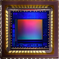
... SOC Megapixel CMOS Digital Image Sensor MT9M131I99STC (Pb-Free iCSP) MT9M131C12STC (Pb-Free CLCC) Features ® • DigitalClarity CMOS imaging technology • System-on-a-Chip (SOC)—Completely integrated camera system • Ultra-low power, high fidelity, progressive scan CMOS image sensor • Superior low-light performance • ...

Page 2

General Description The Micron CMOS active-pixel digital image sensor. This device combines the MT9M011 image sensor core with fourth-generation digital image flow processor technology from Micron Imaging. It captures high-quality color images at SXGA resolution. The MT9M131 features DigitalClarity™, Micron’s ...

Page 3

Figure 1: MT9M131 Quantum Efficiency vs. Wavelength 350 PDF:09005aef824c90f2/Source: 09005aef824c90f9 MT9M131_LDS_2.fm - Rev. A 3/07 EN MT9M131: SOC Megapixel Digital Image Sensor 450 550 650 750 Wavelength (nm) Micron ...

Page 4

Functional Overview The MT9M131 is a fully-automatic, single-chip camera, requiring only a power supply, lens, and clock source for basic operation. Output video is streamed through a parallel 8-bit D Figure 2: Functional Block Diagram Sensor Core SCLK S 1,316H ...

Page 5

Internal Architecture Internally, the MT9M131 consists of a sensor core and an IFP. The IFP is divided in two sections: the colorpipe (CP), and the camera controller (CC). The sensor core captures raw Bayer-encoded images that are then input in ...

Page 6

For low-noise operation, the MT9M131 requires separate power supplies for analog and digital. Incoming digital and analog ground conductors can be tied together next to the die. Both power supply rails should be decoupled to ground using ceramic capacitors. The ...

Page 7

Figure 5: 48-Pin CLCC Assignment D GND [4] OUT D [5] OUT D [6] OUT D [7] OUT D GND LSB0 OUT_ D LSB1 OUT_ D GND V DD PDF:09005aef824c90f2/Source: 09005aef824c90f9 MT9M131_LDS_2.fm - ...

Page 8

Table 4: Pin/Ball Descriptions iCSP CLCC Signal Ball Pin CLKIN RESET ADDR SCLK A6 44 STANDBY DATA TEST_EN OUT ...

Page 9

Sensor Core Overview The sensor consists of a pixel array of 1316 x 1048 total, an analog readout chain, 10-bit ADC with programmable gain and black offset, and timing and control. Figure 6: Sensor Core Block Diagram Active Pixel Sensor ...

Page 10

Electrical Specifications Table 5: Electrical Characteristics and Operating Conditions T = Ambient = 25°C A Parameter I/O digital voltage ( Core digital voltage ( Analog voltage ( Pixel supply voltage (VAAPIX) Leakage current Operating ...

Page 11

Caution Stresses above those listed in Table 7 may cause permanent damage to the device. Table 7: Absolute Maximum Ratings Symbol V SUPPLY I SUPPLY I GND OUT T STG Notes: 1. These are stress ratings only, ...

Page 12

Package Dimensions The MT9M131 comes in two packages: the 44-ball iCSP package, shown in Figure 9, and the 48-pin CLCC package, shown in Figure 10 on page 13. Figure 9: 44-Ball iCSP Package SEATING PLANE A 0.10 A (FOR REFERENCE ...

Page 13

Figure 10: 48-Pin CLCC Package D Seating plane A 8.8 0.8 47X 4.4 TYP 1.0 ±0 48X 0.40 ±0.05 8.8 4.4 4X 0.2 5.215 5.715 11.43 Lead finish: Au plating, 0.50 microns minimum thickness over Ni plating, 1.27 ...

Page 14

Revision History Rev ...

Related keywords