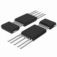
KMA200,115 NXP Semiconductors, KMA200,115 Datasheet - Page 8

KMA200,115
Manufacturer Part Number
KMA200,115
Description
IC SENSOR PROG ANGLE SOT637
Manufacturer
NXP Semiconductors
Datasheet
1.KMA200115.pdf
(32 pages)
Specifications of KMA200,115
Position - Sensing
180°
Sensor Type
Angular - Magnetoresistive
Voltage - Supply
4.5 V ~ 5.5 V
Operating Temperature
-40°C ~ 160°C
Package / Case
SOT-637
Supply Voltage (max)
5.5 V
Supply Voltage (min)
4.5 V
Supply Current
12 mA
Maximum Operating Temperature
+ 160 C
Minimum Operating Temperature
- 40 C
Mounting Style
Through Hole
Product
Programmable Angle Sensor
Lead Free Status / RoHS Status
Lead free / RoHS Compliant
Lead Free Status / RoHS Status
Lead free / RoHS Compliant, Lead free / RoHS Compliant
Other names
568-4286-2
934056510115
KMA200 T/R
934056510115
KMA200 T/R
Available stocks
Company
Part Number
Manufacturer
Quantity
Price
Company:
Part Number:
KMA200,115
Manufacturer:
AD
Quantity:
203
NXP Semiconductors
7. Outputs of KMA200
KMA200_7
Product data sheet
The output of the KMA200 is either digital or analog, depending on the control word stored
in the EEPROM. The analog output consists of a standard and a programmable output
stage. The programmable output stage allows four different characteristics; mode 1,
mode 2, mode 3 or none output. The digital output has two different modes; mode 5 and
mode 6.
Analog output
In the analog output mode the measured angle value is converted linear into a value that
is ratiometric to the supply voltage V
stage to pin DATA/OUT1. The same value is fed to a second output stage that is
connected to pin CLK/OUT2. This second output stage is programmable to one of four
different output characteristics; mode 1, mode 2, mode 3 or high-impedance state output.
A valid angle value is nominally mapped to an output voltage range of V
(default = 5 %) to V
(see
For mode 1 the valid output voltage range at pin CLK/OUT2 is identical to the output
voltage range of the standard analog voltage but the output characteristic is inverted
(see
In mode 2 (see
V
A further possibility is to program the V
from the angle value (see
When the KMA200 detects an error condition, it switches the analog outputs into
high-impedance state. The outputs are forced to lie in the upper or lower diagnostic range
by the external pull-up or pull-down resistors.
Table 5.
Output characteristics
Mode
Mode 1
Mode 2
Mode 3
Mode 4
Mode 5
Mode 6
(CL)u
Figure
Figure
/2 of V
Setting the KMA200 output characteristics
3).
4).
DD
Type
analog
analog
analog
analog
digital
digital
.
Figure
(CL)u
5) the valid output range at pin CLK/OUT2 is nominally V
Rev. 07 — 18 July 2008
(default = 95 %) of V
Pin assignment
DATA/OUT1
standard
standard
standard
standard
serial data (SPI) (clock)
bit complement
serial data (SPI)
Figure
6).
DD
. This voltage is driven by the standard output
OUT2
CLK/OUT2
inverted
half range
comparator
high-impedance state
(clock)
(mode 3,
DD
at the standard output V
thresh
Programmable angle sensor
) as a comparator depending
Mode setting of EEPROM
(ctrl1)
OM2
1
1
1
1
0
0
© NXP B.V. 2008. All rights reserved.
KMA200
(CL)l
OM1
0
0
1
1
0
0
OUT1
(CL)l
OM0
0
1
0
1
0
1
/2 to
8 of 32


