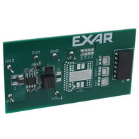
SP7600EB Exar Corporation, SP7600EB Datasheet - Page 5

SP7600EB
Manufacturer Part Number
SP7600EB
Description
EVAL BOARD FOR SP7600
Manufacturer
Exar Corporation
Specifications of SP7600EB
Current - Output / Channel
2A
Outputs And Type
1, Non-Isolated
Features
PWM Brightness control
Voltage - Input
4.5 ~ 29 V
Utilized Ic / Part
SP7600
Maximum Operating Temperature
+ 85 C
Minimum Operating Temperature
- 40 C
Product
Display Modules
Core Chip
SP7600
No. Of Outputs
1
Output Current
2A
Output Voltage
200mV
Dimming Control Type
PWM
Development Tool Type
Hardware - Eval/Demo Board
Mcu Supported Families
SP7600
Lead Free Status / RoHS Status
Contains lead / RoHS non-compliant
Voltage - Output
-
Lead Free Status / Rohs Status
Lead free / RoHS Compliant
Other names
1016-1233
TYPICAL PERFORMANCE CHARACTERISTICS
The typical performance characteristics follow and begin with an illustration of the efficiencies that
can be obtained with the SP7600 driving 1 or 6 white LEDs in series for up to 2A output current.
For the 6 LED applications with a 24V input, the duty cycle is high and an efficiency of 94% can be
obtained. For 12V input and 1 LED at 2A output, the duty cycle is much lower, but the efficiency is
still over 80%. Note: to improve line regulation a small 22pF ceramic capacitor C6 should be placed
from VFB to GND to filter out any noise obtained on the sensitive FB pin.
Scope photos of output ripple are shown for the typical application circuit for 6V input at 150mVpp
ripple and at 29V input with over 400mVpp output ripple, both shown with no output capacitor. For
comparison, an output ripple scope photo is shown with only 70mVpp when a 1uF capacitor is used
at the output. For applications sensitive to output ripple, adding this relatively small 1206 sized 1uF
50V ceramic capacitor to the output provides a very good reduction in output ripple but since the
value is only 1uF the circuit will still provide good PWM output response.
Vin startup scope photos are shown for 6V, 12V and 29V input with no problems in startup as
shown in the Vout, VFB and especially the inductor current signal ILX.
The last scope photos are for the output short circuit which causes a hiccup mode. The output can
be shorted which causes a controlled automatic reset or hiccup mode of about 50 to 100msec
period.
All data taken at V
section of this datasheet.
© 2009 Exar Corporation
Fig. 4: Efficiency vs Input Voltage
IN
= 12V, T
A
= 25°C, unless otherwise specified - Schematic and BOM from Application Information
2
2
A
A
2
2
9
9
V
V
N
N
5/13
o
o
n
n
-
-
S
S
y
y
n
n
c
c
Fig. 5: Output Current vs Input Voltage
.
.
B
B
u
u
c
c
k
k
H
H
i
i
g
g
h
h
P
P
o
o
w
w
e
e
r
r
L
L
E
E
S
S
D
D
P
P
Rev. 2.0.0
D
D
7
7
r
r
6
6
i
i
v
v
0
0
e
e
0
0
r
r


