SP7600EB Exar Corporation, SP7600EB Datasheet - Page 4
SP7600EB
Manufacturer Part Number
SP7600EB
Description
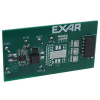
EVAL BOARD FOR SP7600
Manufacturer
Exar Corporation
Specifications of SP7600EB
Current - Output / Channel
2A
Outputs And Type
1, Non-Isolated
Features
PWM Brightness control
Voltage - Input
4.5 ~ 29 V
Utilized Ic / Part
SP7600
Maximum Operating Temperature
+ 85 C
Minimum Operating Temperature
- 40 C
Product
Display Modules
Core Chip
SP7600
No. Of Outputs
1
Output Current
2A
Output Voltage
200mV
Dimming Control Type
PWM
Development Tool Type
Hardware - Eval/Demo Board
Mcu Supported Families
SP7600
Lead Free Status / RoHS Status
Contains lead / RoHS non-compliant
Voltage - Output
-
Lead Free Status / Rohs Status
Lead free / RoHS Compliant
Other names
1016-1233


PIN DESCRIPTION
ORDERING INFORMATION
“YY” = Year – “WW” = Work Week – “L” = Lead Free designator – “X” = Lot Number
© 2009 Exar Corporation
SP7600EN2-L
SP7600EN2-L/TR
SP7600EB
Part Number
Power PAD
Name
SVIN
PVIN
ISET
GND
VDR
FB
LX
Pin Number
SP7600 Evaluation Board
-40°C≤T
-40°C≤T
Temperature
4,5
1
2
3
7
6
8
9
Range
J
J
≤+125°C
≤+125°C
Regulator feedback input. A current setting resistor is connected to LED’s cathode and
FB on one side and to ground on the other side. This pin can be also used for dimming
control. By connecting a diode between this pin and a >2V signal the LED can be pulsed
at up to 1kHz
Ground pin
Power supply for the internal driver. This voltage is internally regulated to about 5V
below VIN. Place a 0.1uF decoupling capacitor between VDR and Vin as close as
possible to the IC.
Connection to the FET source
Input power supply for the regulator. Place input decoupling capacitor as close as
possible to this pin. This is the Vin connection for the regulator and is not tied to the
high-side FET.
Connect to the output inductor. This is the P-Channel FET Drain
This pin is used as a current limit input for the internal current limit comparator.
Connect to LX through an optional resistor. Internal threshold is pre-set to 350mV
nominal and can be decreased by changing the external resistor based on the following
formula: VTRSHLD = 350mV – 33uA * R
Can be connected to inductor LX node for a thermal PAD – see Layout suggestions
section.
Marking
SP7600E
SP7600E
YYWWL
YYWWL
X..X
X..X
2
2
A
A
2
2
9
9
V
V
HSOICN-8
HSOICN-8
Package
Exp. PAD
Exp. PAD
N
N
4/13
o
o
n
n
-
-
S
S
y
y
2.5K/Tape & Reel Lead Free
n
n
c
Quantity
c
Description
Packing
.
.
Bulk
B
B
u
u
c
c
k
k
H
H
Lead Free
i
i
g
g
h
h
Note 1
P
P
o
o
w
w
e
e
r
r
L
L
E
E
S
S
D
D
Note 2
P
P
Rev. 2.0.0
D
D
7
7
r
r
6
6
i
i
v
v
0
0
e
e
0
0
r
r
Related parts for SP7600EB
Image
Part Number
Description
Manufacturer
Datasheet
Request
R

Part Number:
Description:
2amp, 29v Buck Converter For Led Driver Applications
Manufacturer:
Exar Corporation
Datasheet:
Part Number:
Description:
BiCMOS Fixed, Quad, Voltage Output, Single or Dual Supply 8-Bit Digital-to-Analog Converter
Manufacturer:
Exar Corporation
Datasheet:
Part Number:
Description:
Manufacturer:
Exar Corporation
Datasheet:
Part Number:
Description:
Voltage-Controlled Oscillator
Manufacturer:
Exar Corporation
Datasheet:
Part Number:
Description:
INTEGRATED LINE TRANSMITTER
Manufacturer:
Exar Corporation
Datasheet:
Part Number:
Description:
Monolithic Function Generator
Manufacturer:
Exar Corporation
Datasheet:
Part Number:
Description:
CMOS Microprocessor Compatible Double-Buffered 12-Bit Digital-to-Analog Converter
Manufacturer:
Exar Corporation
Datasheet:
Part Number:
Description:
CMOS 6 BIT HIGH SPEED ANALOG TO DIGITAL CONVERTER
Manufacturer:
Exar Corporation
Datasheet:
Part Number:
Description:
Manufacturer:
Exar Corporation
Datasheet:
Part Number:
Description:
Manufacturer:
Exar Corporation
Datasheet:
Part Number:
Description:
8-Channel, Voltage Output 10 MHz Input Bandwidth 8-Bit Multiplying DACs with Serial Digital Data Por
Manufacturer:
Exar Corporation
Datasheet:
Part Number:
Description:
15 V CMOS Multiplying10-Bit Digital-to-Analog Converter
Manufacturer:
Exar Corporation
Datasheet:
Part Number:
Description:
Monolithic Function Generator
Manufacturer:
Exar Corporation
Datasheet: