SP7600EB Exar Corporation, SP7600EB Datasheet
SP7600EB
Specifications of SP7600EB


Related parts for SP7600EB

SP7600EB Summary of contents
Page 1
... SP7600 inputs and outputs so that the user can quickly connect and measure electrical characteristics and waveforms. The Evaluation Board schematic diagram is shown in Figure 1. __________________________________________________________ BOARD SCHEMATIC Figure 1.The SP7600 Evaluation Board Schematic Diagram Rev B 1/8/08 SP7600 Evaluation Board Manual SP7600 Copyright 2007 Exar Corporation ...
Page 2
... Iout = Vfb/RA where RA is the parallel combination of Ra and any of the resistors Rb Rd. If Ra, Rb, Rc and Rd are used then RA = 1/(1/Ra + 1/Rb + 1/Rc + 1/Rd) Standard SP7600EB Evaluation Board Example: Iout = Vfb/RA = 200mV/0.22ohm = 1A 3) Dimming The SP7600 can be pulse width modulated using a signal applied to the DIM post. The DIM signal connects to the VFB pin through a 1N4148 diode and will shutdown the SP7600 when DIM = H and turn- on the SP7600 when DIM = L ...
Page 3
... Figure 4. LED Duty Cycle Vs (1-D) DIM pin Duty Cycle with 12Vin, 2 Luxeon K2s in parallel at 2A 12/17/07 LED Duty Cycle vs 1‐D 100Hz, 2A 90 200Hz, 2A 80 500Hz, 2A 70 1000Hz, (1‐D) PWM Signal (%) total SP7600 Evaluation Board Manual Page 100 © 2007 Exar Corporation ...
Page 4
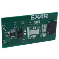
... EVALUATION BOARD LAYOUT Figure 5. SP7600 Evaluation Board Layout top Figure 6. SP7600 Evaluation Board Layout bottom 12/17/07 SP7600 Evaluation Board Manual Page © 2007 Exar Corporation ...
Page 5
... Vector Electronic Table1. SP7600EB List of Materials _____________________________________________________ ORDERING INFORMATION Model SP7600EB............................................. -40°C to +85°C..................................... SP7600 Evaluation Board For further assistance: Email: EXAR Technical Documentation: EXAR Corporation reserves the right to make changes to the products contained in this publication in order to improve design, performance or reliability. EXAR Corporation assumes no responsibility for the use of any circuits described herein, conveys no license under any patent or other right, and makes no representation that the circuits are free of patent infringement ...