SP7600EB Exar Corporation, SP7600EB Datasheet - Page 11
SP7600EB
Manufacturer Part Number
SP7600EB
Description
EVAL BOARD FOR SP7600
Manufacturer
Exar Corporation
Specifications of SP7600EB
Current - Output / Channel
2A
Outputs And Type
1, Non-Isolated
Features
PWM Brightness control
Voltage - Input
4.5 ~ 29 V
Utilized Ic / Part
SP7600
Maximum Operating Temperature
+ 85 C
Minimum Operating Temperature
- 40 C
Product
Display Modules
Core Chip
SP7600
No. Of Outputs
1
Output Current
2A
Output Voltage
200mV
Dimming Control Type
PWM
Development Tool Type
Hardware - Eval/Demo Board
Mcu Supported Families
SP7600
Lead Free Status / RoHS Status
Contains lead / RoHS non-compliant
Voltage - Output
-
Lead Free Status / Rohs Status
Lead free / RoHS Compliant
Other names
1016-1233


DESIGN EXAMPLE
Design a drive circuit for a 1.5A LED with a
12V input voltage. Nominal LED voltage is
3.6V.
A standard value of 0.12ohm 0805 is selected.
An inductor of 4.7uH, rated at 3A
I
A 10µF C
From Equ.4, the ripple current rating of C
a fraction of 1.5A. A 10uF/16V ceramic
capacitor easily meets this requirement and
offers low ESR and ESL.
LAYOUT CONSIDERATION
i) Place the bypass capacitors C4 and C5 as
close as possible to the 7600 IC. See figure 5
for details.
ii) Create a pad under the IC that connects the
power pad (pin 9) to the inductor. Duplicate
this pad through the pcb layers if present, and
on the bottom side of the PCB. Use multiple
vias to connect these layers to aid in heat
dissipation. Do not oversize this pad - since
the LX node is subjected to very high dv/dt
voltages,
between these islands and the surrounding
circuitry will tend to couple switching noise
iii) Connect the Schottky diode cathode as
close as possible to the LX node and inductor
input side. Connect the anode to a large
diameter trace or a copper area that connects
the input ground to the output ground.
iv) The output capacitor, if used, should be
placed close to the load. Use short wide
© 2009 Exar Corporation
SAT
Resistor RFB calculation
Inductor L1 calculation
Input capacitor
is selected.
L
1
=
IN
12
the
3
(C1) is needed (refer to table 1).
V
RFB
6 .
V
×
1
×
3 .
stray
=
(
12
MHz
1
0
V
5 .
2 .
V
A
−
×
3
capacitance
=
. 0
6 .
. 0
45
V
13
)
A
Ω
=
4
3 .
RMS
2
2
μ
A
H
A
and 3A
formed
2
2
IN
9
9
V
V
is
11/13
N
N
o
o
n
n
Voltage rating should be 30V. B340A rated at
30V/3A or equivalent can be used for its
ample current rating and low forward voltage.
Use standard resistor value for Rs of 470Ω.
copper regions to connect output capacitors to
load to minimize inductance and resistances.
v) Keep other sensitive circuits and traces
away from the LX node in particular and away
from the power supply completely if possible.
For more detail on the SP7600 layout see the
SP7600EB Evaluation Board Manual available
on our web site. Each layer is shown in detail
as well as a complete bill of materials.
-
-
Rs
S
S
Schottky current rating I
Rs calculation
y
y
=
n
n
. 0
c
c
35
.
.
B
V
B
Fig. 18: Circuit for design example
I
u
F
u
−
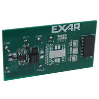
Fig. 19: SP7600 Eval Board
c
c
≥
1 (
k
k
5 .
Component Side Lay
1
H
H
×
−
. 1
i
i
3
g
12
g
05
33
3 .
h
h
V
V
μ
×
P
P
A
×
. 2
o
o
1
25
5 .
w
w
A
A
F
e
e
×
r
=
r
. 0
1
L
L
3 .
095
E
E
S
S
A
D
D
P
P
Ω
Rev. 2.0.0
D
D
)
7
7
=
r
r
6
6
i
i
424
v
v
0
0
e
e
0
0
r
r
Ω
Related parts for SP7600EB
Image
Part Number
Description
Manufacturer
Datasheet
Request
R

Part Number:
Description:
2amp, 29v Buck Converter For Led Driver Applications
Manufacturer:
Exar Corporation
Datasheet:
Part Number:
Description:
BiCMOS Fixed, Quad, Voltage Output, Single or Dual Supply 8-Bit Digital-to-Analog Converter
Manufacturer:
Exar Corporation
Datasheet:
Part Number:
Description:
Manufacturer:
Exar Corporation
Datasheet:
Part Number:
Description:
Voltage-Controlled Oscillator
Manufacturer:
Exar Corporation
Datasheet:
Part Number:
Description:
INTEGRATED LINE TRANSMITTER
Manufacturer:
Exar Corporation
Datasheet:
Part Number:
Description:
Monolithic Function Generator
Manufacturer:
Exar Corporation
Datasheet:
Part Number:
Description:
CMOS Microprocessor Compatible Double-Buffered 12-Bit Digital-to-Analog Converter
Manufacturer:
Exar Corporation
Datasheet:
Part Number:
Description:
CMOS 6 BIT HIGH SPEED ANALOG TO DIGITAL CONVERTER
Manufacturer:
Exar Corporation
Datasheet:
Part Number:
Description:
Manufacturer:
Exar Corporation
Datasheet:
Part Number:
Description:
Manufacturer:
Exar Corporation
Datasheet:
Part Number:
Description:
8-Channel, Voltage Output 10 MHz Input Bandwidth 8-Bit Multiplying DACs with Serial Digital Data Por
Manufacturer:
Exar Corporation
Datasheet:
Part Number:
Description:
15 V CMOS Multiplying10-Bit Digital-to-Analog Converter
Manufacturer:
Exar Corporation
Datasheet:
Part Number:
Description:
Monolithic Function Generator
Manufacturer:
Exar Corporation
Datasheet: