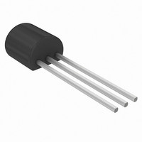
J111,126 NXP Semiconductors, J111,126 Datasheet - Page 3

J111,126
Manufacturer Part Number
J111,126
Description
TRANSISTOR N-CH 40V 50MA SOT54
Manufacturer
NXP Semiconductors
Datasheet
1.J112126.pdf
(6 pages)
Specifications of J111,126
Package / Case
TO-226-3, TO-92-3 (TO-226AA)
Current - Drain (idss) @ Vds (vgs=0)
20mA @ 15V
Drain To Source Voltage (vdss)
40V
Fet Type
N-Channel
Voltage - Breakdown (v(br)gss)
40V
Voltage - Cutoff (vgs Off) @ Id
10V @ 1µA
Input Capacitance (ciss) @ Vds
6pF @ 10V (VGS)
Resistance - Rds(on)
30 Ohm
Mounting Type
Through Hole
Power - Max
400mW
Configuration
Single
Mounting Style
Through Hole
Transistor Polarity
N-Channel
Drain Source Voltage Vds
40 V
Gate-source Cutoff Voltage
3 V
Gate-source Breakdown Voltage
40 V
Drain Current (idss At Vgs=0)
20 mA
Power Dissipation
400 mW
Lead Free Status / RoHS Status
Lead free / RoHS Compliant
Other names
568-5810-2
J111,126
J111,126
Philips Semiconductors
RATINGS
Limiting values in accordance with the Absolute Maximum System (IEC 134)
THERMAL RESISTANCE
STATIC CHARACTERISTICS
T
July 1993
Drain-source voltage
Gate-source voltage
Gate-drain voltage
Gate forward current (DC)
Total power dissipation
Storage temperature range
Junction temperature
From junction to ambient in free air
Gate reverse current
Drain cut-off current
Drain saturation current
Gate-source breakdown voltage
Gate-source cut-off voltage
Drain-source on-state resistance
j
= 25 C unless otherwise specified
N-channel silicon field-effect transistors
up to T
V
V
V
V
V
I
DS
DS
DS
DS
G
GS
= 1 A; V
= 5 V; V
= 15 V; V
= 0.1 V; V
= 5 V; I
= 15 V; V
amb
= 50 C
D
DS
GS
GS
= 1 A
GS
DS
= 0
= 10 V
= 0
= 0
= 0
I
R
DSS
I
I
V
V
DSon
GSS
DSX
(BR)GSS
GS off
I
P
T
T
R
G
V
V
V
stg
j
tot
th j-a
DS
GSO
GDO
3
max.
max.
min.
min.
min.
max.
max.
max.
max.
max.
max.
max.
max.
=
J111
20
40
10
30
1
1
3
J112
J111; J112; J113
65 to
40
50
1
1
5
1
5
Product specification
400 mW
150
150
250 K/W
J113
40 V
40 V
40 V
50 mA
100
0.5
40
1
1
2
3
C
C
nA
nA
mA
V
V
V


