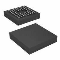
CY7C68053-56BAXIT Cypress Semiconductor Corp, CY7C68053-56BAXIT Datasheet - Page 8

CY7C68053-56BAXIT
Manufacturer Part Number
CY7C68053-56BAXIT
Description
CY7C68053-56BAXIT
Manufacturer
Cypress Semiconductor Corp
Series
MoBL-USB™r
Datasheet
1.CY7C68053-56BAXI.pdf
(42 pages)
Specifications of CY7C68053-56BAXIT
Applications
USB Microcontroller
Core Processor
8051
Program Memory Type
ROMless
Controller Series
CY7C680xx
Ram Size
16K x 8
Interface
I²C, USB
Number Of I /o
56
Voltage - Supply
1.71 V ~ 1.89 V
Operating Temperature
-40°C ~ 85°C
Mounting Type
Surface Mount
Package / Case
56-VFBGA
Processor Series
CY7C68xx
Core
8051
Data Bus Width
8 bit
Data Ram Size
16 KB
Interface Type
I2C
Maximum Clock Frequency
48 MHz
Number Of Programmable I/os
24
Maximum Operating Temperature
+ 85 C
Mounting Style
SMD/SMT
Minimum Operating Temperature
- 40 C
Lead Free Status / RoHS Status
Lead free / RoHS Compliant
For Use With
CY3687 - KIT DEV MOBL-USB FX2LP18
Lead Free Status / Rohs Status
Details
Available stocks
Company
Part Number
Manufacturer
Quantity
Price
Company:
Part Number:
CY7C68053-56BAXIT
Manufacturer:
Cypress Semiconductor Corp
Quantity:
10 000
3.12.4 Endpoint Configurations (High Speed Mode)
Endpoints 0 and 1 are the same for every configuration. Endpoint
0 is the only CONTROL endpoint, and endpoint 1 can be either
BULK or INTERRUPT. The endpoint buffers can be configured
in any one of the 12 configurations shown in the vertical columns
of
first 64 bytes of each buffer are used. For example, in high speed
3.12.5 Default Full Speed Alternate Settings
Table 4. Default Full Speed Alternate Settings
Document # 001-06120 Rev *J
Notes
ep0
ep1out
ep1in
ep2
ep4
ep6
ep8
3. ‘0’ means ‘not implemented.’
4. ‘2×’ means ‘double buffered.’
Figure
Alternate Setting
5. When operating in full speed BULK mode only the
EP0 IN&OUT
EP1 OUT
EP1 IN
EP8
EP2
EP4
EP6
512
512
512
512
512
512
512
512
1
64
64
64
EP4
EP6
EP2
512
512
512
512
512
512
512
512
64
64
64
2
64
0
0
0
0
0
0
0
EP2
EP4
EP6
1024
1024
512
512
512
512
64
64
64
3
64
64 bulk
64 bulk
64 bulk out (2×)
64 bulk out (2×)
64 bulk in (2×)
64 bulk in (2×)
Figure 5. Endpoint Configuration
[3, 4]
EP2
EP8
EP6
512
512
512
512
512
512
512
512
64
64
64
4
1
EP2
EP6
512
512
512
512
512
512
512
512
64
64
64
5
EP2
EP6
1024
1024
the maximum packet size is 512 bytes, but in full speed it is 64
bytes. Even though a buffer is configured to be a 512 byte buffer,
in full speed only the first 64 bytes are used. The unused
endpoint buffer space is not available for other operations. An
example endpoint configuration is:
EP2–1024 double buffered; EP6–512 quad buffered (column 8).
512
512
512
512
64
64
64
6
64
64 int
64 int
64 int out (2×)
64 bulk out (2×)
64 int in (2×)
64 bulk in (2×)
EP2
EP6
EP8
1024
1024
512
512
512
64
64
64
512
7
EP2
1024
1024
EP6
512
512
512
64
64
64
512
8
2
EP2
EP6
1024
1024
1024
1024
64
64
64
9
EP2
EP6
EP8
512
512
512
512
512
512
512
512
64
64
64
10
64
64 int
64 int
64 iso out (2×)
64 bulk out (2×)
64 iso in (2×)
64 bulk in (2×)
EP2 EP2
EP8
1024
1024
1024
1024
64
64
64
512
512
11
CY7C68053
1024
1024
1024
1024
12
64
64
64
3
Page 8 of 42
[+] Feedback


