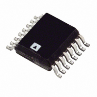
ADT7470ARQZ-REEL Analog Devices Inc, ADT7470ARQZ-REEL Datasheet - Page 14

ADT7470ARQZ-REEL
Manufacturer Part Number
ADT7470ARQZ-REEL
Description
IC,Motor Controller,SSOP,16PIN
Manufacturer
Analog Devices Inc
Datasheet
1.ADT7470ARQZ.pdf
(40 pages)
Specifications of ADT7470ARQZ-REEL
Function
Fan Control, Temp Monitor
Topology
ADC, Comparator, Fan Speed Control, Register Bank
Sensor Type
External
Sensing Temperature
External Sensor
Output Type
I²C™
Output Alarm
No
Output Fan
Yes
Voltage - Supply
3 V ~ 5.5 V
Operating Temperature
-40°C ~ 125°C
Mounting Type
Surface Mount
Package / Case
16-QSOP
Lead Free Status / RoHS Status
Lead free / RoHS Compliant
For Use With
EVAL-ADT7470EBZ - BOARD EVALUATION FOR ADT7470
Lead Free Status / RoHS Status
Lead free / RoHS Compliant
Available stocks
Company
Part Number
Manufacturer
Quantity
Price
Part Number:
ADT7470ARQZ-REEL7
Manufacturer:
ADI/亚德诺
Quantity:
20 000
ADT7470
TEMPERATURE READBACK BY THE HOST
The user cannot read the ADT7470 temperature register values
if the ADT7470 is in the process of a temperature measurement.
The user must wait until the data from all the TMP05s and
TMP06s in the chain are received by the ADT7470 before
reading these values. Otherwise, the temperature registers
may store an incorrect value. It is recommended to wait at
least 200 ms for each TMP05 and TMP06 in the chain. The
recommended procedure is as follows:
1.
2.
3.
4.
TEMPERATURE DATA FORMAT
Temperature data on the ADT7470 is stored in an 8-bit format,
with the 7 LSBs being the temperature, and the MSB acting as
the sign bit. Use the following formulae when reading back
from the temperature registers, o calculate the temperature:
Positive Temperature = ADC Code (decimal)
Negative Temperature = ADC (decimal) minus 256
For negative temperature readings, the MSB is always set to 1.
Set Register 40 Bit[7] = 1. This starts the temperature
measurements.
Wait 200 ms for each TMP05/TMP06 in the loop.
Set Register 40 Bit[7] = 0.
Read the temperature registers.
ADT7470
TMP_START
Figure 14. Typical Timing Diagram of ADT7470 with Two TMP05s Connected in Daisy-Chain Mode
TMP_IN
NOTES:
t
t
t
EACH START/STOP PULSE IS TYPICALLY 25μs.
TMP05s MUST BE IN DAISY-CHAIN MODE.
SEE THE TMP05 DATA SHEET FOR MORE INFORMATION.
START
1 STOP
2 STOP
IS GENERATED BY THE ADT7470 AND IS THE START PULSE FOR TMP05 1.
IS GENERATED BY TMP05 2.
IS GENERATED BY TMP05 1 AND IS THE START PULSE FOR TMP05 2.
t
ADT7470
START
t
40ms
1 HIGH
TMP05 1
TEMP = 25°C
Rev. C | Page 14 of 40
t
1
76ms
t
1 LOW
t
1 STOP
Example:
1.
2.
3.
4.
Table 8. Temperature Data Format
Temperature (°C)
−128
−125
−100
−75
−50
−25
−10
+0
+10
+25
+50
+75
+100
+125
+175
t
Temperature read back from register 0x20: 0xFF.
Convert into decimal format. 0xFF = 255 (decimal).
Check if MSB is set to 1. It is in this example. Therefore,
use negative temperature formula, ADC (d) minus 256.
Temperature = 255 − 256 = −1°C.
40ms
2 HIGH
TMP05 2
TEMP = 120°C
t
2
100ms
t
2 LOW
Digital Output (8 Bit)
1000 0000
1000 0011
1001 1100
1011 0101
1100 1110
1110 0111
1111 0110
0000 0000
0000 1010
0001 1001
0011 0010
0100 1011
0110 0100
0111 1101
0111 1111
t
2 STOP


