ADSP-21262SBBC-150 Analog Devices Inc, ADSP-21262SBBC-150 Datasheet - Page 18
ADSP-21262SBBC-150
Manufacturer Part Number
ADSP-21262SBBC-150
Description
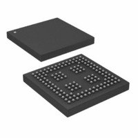
IC,DSP,32-BIT,CMOS,BGA,136PIN,PLASTIC
Manufacturer
Analog Devices Inc
Series
SHARC®r
Type
Fixed/Floating Pointr
Specifications of ADSP-21262SBBC-150
Interface
DAI, SPI
Clock Rate
150MHz
Non-volatile Memory
ROM (512 kB)
On-chip Ram
256kB
Voltage - I/o
3.30V
Voltage - Core
1.20V
Operating Temperature
-40°C ~ 85°C
Mounting Type
Surface Mount
Package / Case
136-CSPBGA
Device Core Size
32/40Bit
Architecture
Super Harvard
Format
Floating Point
Clock Freq (max)
150MHz
Mips
150
Device Input Clock Speed
150MHz
Ram Size
256KB
Program Memory Size
512KB
Operating Supply Voltage (typ)
1.2/3.3V
Operating Supply Voltage (min)
1.14/3.13V
Operating Supply Voltage (max)
1.26/3.47V
Operating Temp Range
0C to 70C
Operating Temperature Classification
Commercial
Mounting
Surface Mount
Pin Count
136
Package Type
CSPBGA
Lead Free Status / RoHS Status
Contains lead / RoHS non-compliant
Lead Free Status / RoHS Status
Contains lead / RoHS non-compliant
Available stocks
Company
Part Number
Manufacturer
Quantity
Price
Company:

Part Number:
ADSP-21262SBBC-150
Manufacturer:
Analog Devices Inc
Quantity:
10 000


ADSP-21261/ADSP-21262/ADSP-21266
Clock Input
See
Table 16. Clock Input
1
2
3
4
5
6
Clock Signals
The ADSP-2126x can use an external clock or a crystal. See
CLKIN pin description. The programmer can configure the
ADSP-2126x to use its internal clock generator by connecting
the necessary components to CLKIN and XTAL.
the component connections used for a crystal operating in fun-
damental mode. Note that the 200 MHz clock rate is achieved
using a 12.5 MHz crystal and a PLL multiplier ratio 16:1
(CCLK:CLKIN).
Parameter
Timing Requirements
t
t
t
t
f
t
Applies to all 150 MHz models. See
Applies to all 200 MHz models. See
Applies only for CLK_CFG1–0 = 00 and default values for PLL control bits in PMCTL.
Applies only for CLK_CFG1–0 = 01 and default values for PLL control bits in PMCTL.
See
Any changes to PLL control bits in the PMCTL register must meet core clock timing specification t
CK
CKL
CKH
CKRF
vco
CCLK
NOTE: C1 AND C2 ARE SPECIFIC TO CRYSTAL SPECIFIED FOR X1.
CONTACT CRYSTAL MANUFACTURER FOR DETAILS. CRYSTAL
SELECTION MUST COMPLY WITH CLKCFG1-0 = 10 OR = 01.
CLKIN
Table 16
5
Figure 4 on Page 16
Figure 7. 150 MHz or 200 MHz Operation with a 12.5 MHz
C1
CLKIN
CLKIN Period
CLKIN Width Low
CLKIN Width High
CLKIN Rise/Fall (0.4 V to 2.0 V)
VCO Frequency
CCLK Period
and
Figure
for VCO diagram.
Fundamental Mode Crystal
1M
X1
Figure 6. Clock Input
6
t
6.
CKH
Ordering Guide on Page
Ordering Guide on Page
C2
XTAL
t
CK
t
CKL
Figure 7
44.
44.
Rev. F | Page 18 of 44 | July 2009
Min
20
7.5
7.5
200
6.66
3
3
3
shows
150 MHz
3
Max
160
80
80
800
10
4
4
4
1
CCLK
.
Min
15
6
6
200
5
3
3
3
200 MHz
Max
3
160
80
80
800
10
4
4
4
2
Unit
ns
ns
ns
ns
MHz
ns
Related parts for ADSP-21262SBBC-150
Image
Part Number
Description
Manufacturer
Datasheet
Request
R

Part Number:
Description:
±1.7g Dual-Axis IMEMS Accelerometer Evaluation Board
Manufacturer:
Analog Devices Inc
Datasheet:

Part Number:
Description:
Inertial Sensor Evaluation System
Manufacturer:
Analog Devices Inc
Datasheet:
Part Number:
Description:
Manufacturer:
Analog Devices Inc
Datasheet:
Part Number:
Description:
Manufacturer:
Analog Devices Inc
Datasheet:
Part Number:
Description:
Manufacturer:
Analog Devices Inc
Datasheet:
Part Number:
Description:
Manufacturer:
Analog Devices Inc
Datasheet:
Part Number:
Description:
Manufacturer:
Analog Devices Inc
Datasheet:
Part Number:
Description:
Manufacturer:
Analog Devices Inc
Datasheet:
Part Number:
Description:
Manufacturer:
Analog Devices Inc
Datasheet:
Part Number:
Description:
Manufacturer:
Analog Devices Inc
Datasheet:
Part Number:
Description:
Manufacturer:
Analog Devices Inc
Datasheet:
Part Number:
Description:
Manufacturer:
Analog Devices Inc
Datasheet:
Part Number:
Description:
Manufacturer:
Analog Devices Inc
Datasheet: